AllenĆBradley Encoder/Counter Modules (Cat. Nos.
DeviceNet, DeviceNetManager, and RediSTATION are trademarks of Allen-Bradley Company, Inc. PLC, PLC–2, PLC–3, and PLC–5 are registered trademarks of Allen-Bradley Company, Inc. Windows is a trademark of Microsoft. Microsoft is a registered trademark of Microsoft IBM is a registered trademark of International Business Machines, Incorporated. All other brand and product names are trademarks or registered trademarks of their respective companies.
Preface Using This Manual Preface Objectives Read this preface to familiarize yourself with this manual and to learn how to use it properly and efficiently. Audience We assume that you have previously used an Allen-Bradley programmable controller, that you are familiar with its features, and that you are familiar with the terminology we use. If not, read the user manual for your processor before reading this manual.
P–2 Using This Manual Important User Information Because of the variety of uses for the products described in this publication, those responsible for the application and use of these products must satisfy themselves that all necessary steps have been taken to assure that each application and use meets all performance and safety requirements, including any applicable laws, regulations, codes and standards.
Using This Manual Summary P–3 This preface gave you information on how to use this manual efficiently.
P–4 Using This Manual Publication 1771ĆUM006B-EN-P - June 2002
Table of Contents Introduction Chapter 1 General . . . . . . . . . . . . . . . . . . . . . . . . . . . . . . . . . . . . . . . . . . . General Description . . . . . . . . . . . . . . . . . . . . . . . . . . . . . . . . . . . Status Indicators . . . . . . . . . . . . . . . . . . . . . . . . . . . . . . . . . . . . . System Power . . . . . . . . . . . . . . . . . . . . . . . . . . . . . . . . . . . . . . . External Power . . . . . . . . . . . . . . . . . . . . . . . . . . . . . . . . . . . . . .
toc-ii Table of Contents Block Transfer Programming Chapter 6 General . . . . . . . . . . . . . . . . . . . . . . . . . . . . . . . . . . . . . . . . . . . Output Words - Block Transfer . . . . . . . . . . . . . . . . . . . . . . . . . . . Output Control Word . . . . . . . . . . . . . . . . . . . . . . . . . . . . . . . . Preset Words . . . . . . . . . . . . . . . . . . . . . . . . . . . . . . . . . . . . . Example Block Transfer Programs . . . . . . . . . . . . . . . . . . . . . . . .
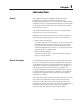
Chapter 1 Introduction General This publication describes installation, adjustments and the programming necessary for communication between the Encoder/Counter Module (cat. no. 1771-IJ,-IK) and a programmable controller processor. The programming techniques given here enable the processor to direct the operation of the encoder/counter module and to monitor its status. The encoder/counter module can be used with any Allen-Bradley processor that uses the 1771 I/O structure.
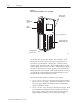
1–2 Introduction Figure 1.1 Encoder Counter Module (cat. no. 1771ĆIJ/IK) Slotted for I/O Insertion Only Brown Identification Label Status indicators Protective Cover Label Identifies User Output Connections Field Wiring Arm Connects Here 15942 The module will count in either BCD or binary numbers. In the BCD mode, the range is 000 to 999 with carry and borrow bits provided to cascade counters in the program.
Introduction 1–3 The encoder/counter module is shipped with two 12 terminal gold-plated Field Wiring Arms (cat. no. 1771-WB). Unless otherwise noted, this manual refers to both versions of the module. Status Indicators There are seven status indicators (Figure 1.2) on the front of the left half of the module. The four indicators, corresponding to channel A, channel B, marker, and switch inputs, illuminate when their respective input signals are high.
1–4 Introduction System Power System power is supplied through the I/O chassis backplane from the 5V dc chassis power supply. The module requires a current of 1.4A. The sum of the current requirements of all modules in the chassis must not exceed the power supply or backplane rating. External Power The module requires an external power supply connected to the field wiring arm. For the 1771-IJ, the supply must be able to deliver 140mA at 5V dc +0.25V with less than 50mV ripple, peak-to-peak.
Chapter 2 Preliminary Adjustments General The module has programming options (Table 2.A) that are selected by setting the five switches on the programming option switch assembly (SW-1). These options include the choices between encoder and counter operation, block transfer or single transfer, BCD or binary data formats and count resolution in the encoder mode. Table 2.A Programming Option Switch Assembly SWĆ1 On Off Block Transfer/Single Transfer 1 2, 3 4 5 Single Transfer See Table 2.
2–2 Preliminary Adjustments Count Resolution Count resolution (switches 2 and 3) - In the encoder mode, the accuracy of a quadrature type encoder can be improved by allowing the module to count the pulse trains at both channel inputs. This doubles the number of pulses counted for the same degree of rotation at the encoder.
Preliminary Adjustments 2–3 Figure 2.1 Input Pulses Time Channel A Encoder Channel B Up Pulsed to Counter x1 x2 x4 Channel A Encoder Channel B x1 Down Pulsed to Counter x2 x4 15945 In the counter mode, the module adds the incoming pulses on channel A. The count is incremented on the rising edge of the pulse (high true). The direction of the count can be controlled with either the control word or an external switch wired to channel B.
2–4 Preliminary Adjustments Binary/BCD Data Format Binary/BCD data format (switch 5) - The preset values and the accumulated total in the status word have the option of appearing in either BCD or binary formats. If the BCD format is selected, the processor can directly manipulate these values in comparisons or arithmetic functions but the accumulated value is limited to a count between 000 and 999. The binary option allows an increased range of 0000 to 409510.
Preliminary Adjustments 2–5 No special filtering is provided on channel B, since the filtering necessary for a mechanical switch would defeat the purpose of a very fast count direction change that is not dependent on the processor scan time. Therefore, a transistor switch or gate should be used to pull the channel B input low. The gate or switch must sink 14ma of current to pull the channel B input low. The count changes direction in less than 0.01ms from the time channel B input changes state.
2–6 Preliminary Adjustments Table 2.D Input Configuration Switch Assembly (1771ĆIK) SWĆ2 Switch 1 Switch 2 Switch 3 On PullĆup PullĆdown Filter in (50 Hz) Off Float Float Filter out (50K Hz) Certain counting devices may need an input designed to pull current down through the device. Switch 2 should be set on for pull-down and switch 1 left off. The module detects a minimum of 7.2V dc at its input channels as true for a 12V dc external supply and 14.4V dc at 24V dc external supply.
Preliminary Adjustments 2–7 No special filtering is provided on channel B, since the filtering necessary for a mechanical switch would defeat the purpose of a very fast count direction change that is not dependent on the processor scan time. Therefore, a transistor switch or gate should be used to pull the channel B input low, sinking 10mA at 12V dc or 20mA at 24V dc. The count changes direction in less than 10 microseconds from the time channel B input changes state.
2–8 Preliminary Adjustments 3. Set the switches of SW-1 (Table 2.E) according to the desired programming options. The settings for the count resolution switches (times 1, 2, or 4) do not matter if the counter mode has been selected. The tip of a ball point pen can be used to set the rocker arm of a switch. Do not use a pencil because the point can break off and jam the switch. 4. Set the three switches of SW-2 (Table 2.E) according to the input configurations that have been chosen. 5.
Chapter 3 Installation Environment and Enclosure ATTENTION ! Environment and Enclosure This equipment is intended for use in a Pollution Degree 2 industrial environment, in overvoltage Category II applications (as defined in IEC publication 60664–1), at altitudes up to 2000 meters without derating. This equipment is considered Group 1, Class A industrial equipment according to IEC/CISPR Publication 11.
3–2 Installation ATTENTION ! Preventing Electrostatic Discharge This equipment is sensitive to electrostatic discharge, which can cause internal damage and affect normal operation. Follow these guidelines when you handle this equipment: • Touch a grounded object to discharge • • • • • Module Placement The module may be placed in any 1771 I/O chassis. However, the module must only be inserted in a single module group; it cannot straddle two groups.
Installation 3–3 Figure 3.
3–4 Installation Figure 3.
Installation Keying 3–5 Plastic keying bands provide an easy method for keying an I/O slot to accept only one type of module. Use of keying bands is strongly recommended to prevent accidental insertion of the wrong type of module. The module is slotted in two places on its rear edge. The position of the keying bands on the backplane connector must correspond to these slots to allow insertion of the module. Because the module uses two slots, both slots have to be keyed.
3–6 Installation Publication 1771ĆUM006B-EN-P - June 2002
4 Chapter Module/Processor Communication General Communication between the processor and the encoder/counter module is bidirectional. This means that information is transferred to and from the module: the processor instructs the module to perform specific functions and may provide values to be compared on the module and used for output control; the module transmits its accumulated count and other status information to the processor.
4–2 Module/Processor Communication Outputs Words The program controls encoder/counter module operation through the output words. These words function as follows: • Control word – the control word, as its name implies, instructs the module on its operation and on control of its own outputs. By setting specific control word bits, you set up the module’s initial mode of operation and can subsequently alter module operation as the application requires.
Module/Processor Communication 4–3 Bits 00–13 of this word show the accumulated count kept by the module. This count may be stored either in BCD form, as 000–999 (decimal) or in 12–bit binary form, as a binary value from 0000 0000 0000 to 1111 1111 1111. A switch selection, set during module installation, determines the numerical form in which the accumulated count is stored. Bits 14–17 of this input word serve as status bits.
4–4 Module/Processor Communication Publication 1771ĆUM006B-EN-P - June 2002
Chapter 5 Single Transfer Programming General Single transfer programming is one method for coordinating and controlling bidirectional module/processor communication. This method can only be used when the module is in a local I/O chassis. Single transfer may be the recommended method even where block transfer capability is available. Specifically, single transfer programming is suggested whenever preset #1 words and #2 are not used.
5–2 Single Transfer Programming Figure 5.1 Control Word Ć Single Transfer Function Control Bits BIT 11 BIT 10 0 0 Count 0 1 Reset, and hold the accumulated count at 000. 1 0 Return the accumulated count to 000 and begin counting immediately. 1 1 Invalid, module executes previously programmed function. FUNCTION Bits 10Ć11, Function Control (see table) Bits 14Ć17, Word Select Bits. Must have this pattern for control word.
Single Transfer Programming 5–3 Note that if a device is wired to channel B for external control of count direction, the up/down bit must be set to 1. Count direction can be externally controlled by using a transistor switch, as described in chapters 2 and 3. Bit 12 is the enable outputs bit. The state of this bit controls module outputs as follows: 1 -Outputs enabled. This means that the output module can be energized based on logical operations performed by the module. 0 -Outputs disabled.
5–4 Single Transfer Programming Bits 00-05 are significant only when one or both preset words are used. These bits establish the comparison conditions for module control of its outputs. As Figure 5.1 shows, bits 00-02 set up parameters for comparison with preset word #1; bits 03-05 set up parameters for comparison with preset word #2. The module then controls its output #1 or #2 based on the true or false comparison of its accumulated count with these presets.
Single Transfer Programming 5–5 Figure 5.3 Preset Word #2 Ć Single Transfer Bits 14Ć17 = Word Select Bits, must have this pattern for Preset Word #2..
5–6 Single Transfer Programming Bidirectional single transfer programming, then, requires both an input image table and an output image table word. The addresses of these image table words depend on the location of the I/O module in the chassis. For example, for modules in I/O rack 1, module group 6, the corresponding output image table word is 016; the input image table word is 116.
Single Transfer Programming 5–7 However, in some applications, one or both preset words must be used. Here, the complication involving the output image table word is readily apparent: it must be used to serve multiple purposes; not only will this word send the output control word, it is also needed to send one or both preset words to the module. The use of this word for more than one purpose is termed multiplexing.
5–8 Single Transfer Programming Rung 4 shows the input status word examined in the user program. Note that this word is automatically in the input image table when single transfer is selected. The processor automatically updates this word each I/O scan. In summary, when you are not using preset words, you need only set bits of the output image table word which corresponds to the module. This word then serves as the output control word.
Single Transfer Programming 5–9 Table 5.A Scan Count Sequencing At Count: [1] Program Executes Command To: I/O Scan: 1 PUT Control word into output word Sends output word 2 PUT Preset word #1 into output word Sends output word 3 PUT Preset word #2 into output word Sends output word [1]This count is the scan counter Accumulated value for PLCĆ2, PLCĆ2/15, PLCĆ2/20, and MiniĆPLCĆ2 Controllers. For the PLC Controller, these values would be doubled: 2, 4, and 6 respectively.
5–10 Single Transfer Programming Figure 5.6 Scan Counter Ć PLCĆ2 Processors 030 CTU PR003 AC000 030 CTU PR003 AC000 Branch End Instruction 15957 The output instruction of both rungs in Figure 5.6 is an up-counter (CTU) instruction. The first rung, since it is unconditional, is always true. The second rung, since a branch end instruction by itself is always false, sets the conditions for the counter as false.
Single Transfer Programming 5–11 In order to keep track of both I/O and program scans, the PLC scan counter rungs manipulate a particular type of memory bit. This must be a bit in the input image table which is not wired to a corresponding input device, so that the bit is turned off each I/O scan.
5–12 Single Transfer Programming Note: In some applications, it may be feasible to designate an input location for the purpose of scan counter control. In this instance, an on-delay timer (TON) instruction can be used to multiplex output data to the encoder/counter module. A timer with 0.1-second resolution is acceptable for this purpose. Each step of Table 5.A can be programmed to be executed at a 0.1-second interval from the previous step. Example Program Ć Single Transfer Figure 5.
Single Transfer Programming 5–13 The following assumptions are made for this sample program: • Encoder/counter module is in I/O rack 1, module group 2. • Output control word is stored in word 051. • Preset words #1 and #2 are stored in words 052 and 053, respectively. • The scan counter is recycled, as shown in rung 6. This allows continuous update of the module should output values be changed by the program.
5–14 Single Transfer Programming Publication 1771ĆUM006B-EN-P - June 2002
Chapter 6 Block Transfer Programming General Block transfer programming is available with all Allen-Bradley processors that use the 1771 I/O structure. Block transfer is specifically intended for use with I/O modules such as the encoder/counter module, that perform more complex operations than simple on/off input sensing or output switching. For the operation of such modules, multiple words of data must be transferred to or from the processor.
6–2 Block Transfer Programming Figure 6.1 Control Word Ć Block Transfer Mode Bit 03, Up/down 1 = count up 0 = count down (Significant in counter mode only) Bits 00Ć01 Function Control (See Table) Bits 05Ć17, Not used.
Block Transfer Programming 6–3 The module indicates it has reset its count to zero by setting the home bit (bit 17 in the input status word). It resets this bit when the home latch enable bit (bit 04) is reset. (Refer to Figure 4.2, Input Status Word).
6–4 Block Transfer Programming Preset Words In block transfer communication, preset words #1 and #2 have the format of Figure 6.2. Here bits 00-13 store the preset value. When BCD operation has been selected, these bits may represent a value from 000-999. When 12-bit binary operation has been selected, the value may range from 0 to 1111 1111 1111 binary (4095 decimal). A module switch selection is made during installation to select either BCD or binary mode. Figure 6.
Block Transfer Programming 6–5 Note that there is no identifying bit pattern to distinguish preset words #1 and #2 from each other. The encoder/counter module identifies these words by their order of transmission in block transfer. As these words are stored in memory, preset word #1 is stored in the word immediately following the output control word. Preset word #2 is then stored in the word immediately following preset word #1.
6–6 Block Transfer Programming Rung Descriptions Rungs 1 and 2 - These rungs request the block transfer write (BTW) and block transfer read (BTR) operations. Rung 3 - When the processor successfully completes a BTR operation, it sets the done (DN) bit and enables the file-to-file move (FFM) instruction. The FFM instruction moves the BTR data file (CCC-DDD) into a storage data file (EEE-FFF). This prevents the processor from using invalid data if a block transfer communications fault should occur.
Block Transfer Programming 6–7 PLCĆ3 Family Processors Use the following ladder logic with PLC-3 or PLC-3/10 processors. This program assumes that your application requires a single BTR and BTW instruction to pass data between the processor and the module. Ladder logic alternates the execution of BTR and BTW instructions. The processor checks data validity before accepting read data, and sets one enable bit at a time. Refer to Figure 6.5 for generalized ladder logic, and to Figure 6.
6–8 Block Transfer Programming Figure 6.
Block Transfer Programming 6–9 PLCĆ5 Family Processors You can use the following ladder logic with PLC-5 processors. This program assumes that your application requires a single BTR and BTW to pass data between the processor and the module. Ladder logic alternates the execution of BTR and BTW instructions. The processor checks data validity before accepting read data, and sets one enable bit at a time. Refer to Figure 6.7 for generalized ladder logic, and to Figure 6.
6–10 Block Transfer Programming Figure 6.
Chapter 7 Special Programming Extending the Count Beyond 999 The input Status word stores a maximum count of 999 (BCD). If using binary resolution, the maximum count is 1111 1111 1111 (4095 binary). To count beyond these full scale values, you may want to use either of the following ladder programs for PLC–2 or PLC–3 family processors. Both programs (Figure 7.1 and Figure 7.2) extend the count beyond 999 (4095 binary) in the same manner.
7–2 Special Programming Figure 7.1 Ladder Logic for Extending the Count Beyond 999 (PLC-2 Program) SUBTRACT PREVIOUS COUNT FROM CURRENT COUNT. STORE IN 0077. 1 CURRENT PREVIOUS SCAN IJ/IK COUNT COUNT 0113 0577 GET GET 125 168 NEW/OLD COUNT DIFF. 0077 043 IF THE DIFFERENCE IS GREATER THAN A CONSTANT (COUNT PASSED THROUGH ZERO), THEN INCREMENT THE COUNT. THE CONSTANT MUST BE LESS THAN 1/2 THE TOTAL COUNTS OF THE IJ/IK (HALF OF 999 OR 4095). 2 NEW/OLD COUNT CONSTANT DIFF.
Special Programming 7–3 Figure 7.
7–4 Special Programming Rung Descriptions (Figure 7.2) Rung 0 – This rung strips the upper byte of the count value and stores the value. A = BTR status B = Mask R = Temporary count storage with upper byte removed A = Temporary count storage with upper byte removed R = New count value Rung 1 – This rung subtracts the old count value from the new value and stores the difference with its sign.
Appendix A Specifications Specifications - 1771ĆIJ and ĆIK Encoder Counter Modules General Input Specifications Number of Counters 1 Counter Input (switch selectable) Single channel (counter) Dual channel (encoder) Input Pulse Rate 50KHz maximum Data Transfer Modes (switch selectable) Single transfer mode Block transfer mode 1771-IJ External supply 5V dc, +0.25V Input Ratings Vin = 0-5V dc Vih (min) = 2.4V dc Vil (max) = 0.6V dc Device driving input terminal must be able to sink 16A minimum.
A–2 Specifications Specifications - 1771ĆIJ and ĆIK Encoder Counter Modules Indicators 2 Channel A and B status 1 Marker 1 Limit 2 Output 1 and 2 1 Red Fault Keying 1771-IJ 1771-IK Left connector: Between 6 and 8; 18 and 20 Right connector: Between 4 and 6; 32 and 34 Left connector: Between 6 and 8; 20 and 22 Right connector: Between 4 and 6; 32 and 34 Note: Modules must be in a single module group (slots 0 and 1). Do not straddle 2 module groups.
Specifications A–3 Specifications - 1771ĆIJ and ĆIK Encoder Counter Modules Field Wiring Arm Wiring Size Insulation Category Certifications (when product is marked) 14-22AWG (2.5-0.25mm2) solid or stranded copper wire rated at 60oC or greater 3/64 inch (1.
A–4 Specifications Publication 1794ĆUM006B-EN-P - June 2002
Index Numbers I 1771-IJ, description, 1-2 indicators, status, 1-3 1771-IK, description, 1-2 input configuration switch, 2-6 input status word, 4-2 B bit description output word for block transfer, 6-3 single transfer, 5-2 block transfer output words, 6-1 preset words, 6-4 block transfer programming, 6-1 example, 6-5 PLCĆ2 example, 6-5 PLCĆ3 example, 6-7 PLCĆ5 example, 6-9 C cable selection, 3-2 communication, between module and processor, 4-1 control word, 4-2 count resolution, 2-2 K keying band pl
I–2 Index S scan counter, PLCĆ2, 5-9 selection cable, 3-2 encoder/counter, 2-2 setting switches, 2-7 single transfer bit description, 5-2 output words, 5-1 preset words, 5-4 status indicators, 1-3 switch data format, 2-4 input configuration, 2-6 settings, 2-7 Publication 1771-UM006B-EN-P - June 2002
AllenĆBradley Publication Problem Report If you find a problem with our documentation, please complete and return this form. Encoder Counter Modules User Manual Pub. Name Cat. No. 1771ĆIJ, 1771-IK Check Problem(s) Type: Pub. No. 1771ĆUM006B-EN-P Pub. Date June 2002 Part No.
Other Comments PLEASE REMOVE I–2 PLEASE FOLD HERE NO POSTAGE NECESSARY IF MAILED IN THE UNITED STATES BUSINESS REPLY MAIL FIRST-CLASS MAIL PERMIT NO.
Support Services At Allen-Bradley, customer service means experienced representatives at Customer Support Centers in key cities throughout the world for sales service and support.
Publication 1771-UM006B-EN-P - June 2002 Supersedes publication 1771-6.5.6 - May 1988 and 1771-6.5.6-RN1 - November 1995 PN957678-18 Copyright 2002 Ć Rockwell Automation, Inc.