
.INSTRUCTIONS ANALOG INPU User guide

Publication 17715.45 - July 1997
Analog Input Module
(Catalog Number 1771-IFE/C)
Use this document as a guide when installing the 1771-IFE/C analog
input module.
To See page
Prevent Electrostatic Discharge Below
Understand Compliance to European Union Directives 2
Understand Product Compatibility 2
Calculate Power Requirements 3
Determine Module Placement 3
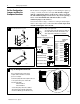
Set the A/B Simulation Jumper 3
Set the Configuration Jumpers 4
Key the Backplane Connector 4
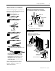
Install the Module and Field Wiring Arm 5
Connect Wiring to the Field Wiring Arm 6
Ground the Chassis and Module 9
Configure the Module 10
For this reference information See page
Status Indicators 12
Troubleshooting 13
Specifications 13
CSA Hazardous Approval 15
Differences Between Series A, B and C Modules 16
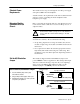
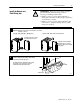
The analog input module is sensitive to electrostatic discharge.
!
ATTENTION: Electrostatic discharge can damage
integrated circuits or semiconductors if you touch
backplane connector pins. Follow these guidelines
when you handle the module:
• Touch a grounded object to discharge static potential
• Wear an approved wrist-strap grounding device
• Do not touch the backplane connector or
connector pins
• Do not touch circuit components inside the module
• If available, use a static-safe work station
• When not in use, keep the module in its
static-shield box
This
icon is used when
additional information
is available in the
Analog
Input Module User Manual
,
publication 17716.5.1
15.
If you need a copy of this
manual, fax the enclosed
User Manual Request Card
to 18005766340. If you
are outside the U.S., fax the
card to13307234036.
Installation Instructions
Contents
Prevent Electrostatic
Discharge