
User guide


Calibrating the Analog Input Module
Chapter 5
56
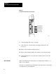
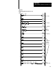
Figure 5.2
Location
of Potentiometers and T
est Points
14163
Potentiometer #1
Potentiometer #2
Potentiometer #3
Red Test Point
Black Test Point
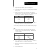
8. Seal the setting with a drop of sealant.
9. Turn off power to the external power supply, I/O chassis, and
processor.
10. Remove the module from the I/O chassis.
11. Reset switch number 2 OFF of the transfer mode switch assembly.
12. After replacing the covers, place the module back in its slot in the
I/O chassis.
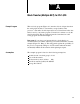
Start your calibration procedure here if your input range is NOT (1 to 5
VDC) or (4 to 20 mA).
You make one adjustment for all channels at the same time for offset, then
one adjustment for gain calibration.
Offset (Part B)