
User guide


Calibrating the Analog Input Module
Chapter 5
54
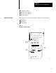
Set these switches as follows:
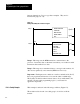
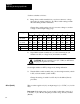
1. Range Select switch assembly lets you select a current or voltage
input range by setting switches 1-10. These switch settings remain
the same during and after calibration.
Change these switch settings only if you want to change to another
voltage or current input range group.
Range: Switch
Number
1 2 3 4 5 6 7 8 9 10
1 to 5V
4 to 20 mA
OFF
OFF
OFF
OFF
ON
ON
ON
ON
OFF
OFF
ON
ON
OFF
OFF
ON
ON
OFF
OFF
OFF
OFF
0 to 5V
0 to 20 mA
ON
ON
ON
ON
OFF
OFF
OFF
OFF
ON
ON
ON
ON
OFF
OFF
ON
ON
OFF
OFF
ON
ON
0 to 10V
ON ON OFF OFF ON ON OFF ON OFF OFF
+10V ON ON OFF OFF ON OFF ON OFF ON OFF
+20mA ON ON OFF OFF ON OFF ON ON OFF OFF
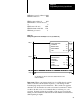
2. Signal Mode switch assembly lets you select current mode (all
switches are ON) or voltage mode (all switches are OFF).
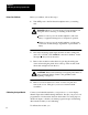
CAUTION: Be sure external power (15, 5 VDC) is OFF before
changing the signal mode switch.
Set all eight switches to OFF (voltage mode) during calibration.
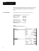
3. Transfer Mode switch assembly lets you select single transfer (switch
1 ON) or block transfer (switch 1 OFF).
Change the setting of switch 2 to ON only for the Offset (Part A)
procedure.
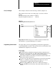
This procedure applies only if your input range is (1 to 5 VDC) or (4 to 20
mA).
Important: If the input range of your module is other than a range of (1
to 5 VDC) or (4 to 20 mA), skip this procedure and go directly to Offset
(Part B).
Offset (Part A)