
User guide


Programming the Analog Input Module
Chapter 4
42
between instructions. Do not copy these examples. They are for
instructional purposes only.
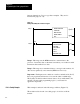
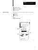
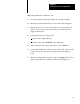
Figure 4.1
Example
ReadOnly Block T
ransfer Program
EN
BLOCK XFER READ
DATA ADDR:
MODULE ADDR:
BLOCK LENGTH:
FILE:
DN
BTR
DN
FILE TO FILE MOVE
COUNTER ADDR:
POSITION:
FILE LENGTH:
FILE A:
FILE R:
RATE PER SCAN:
EN
DN
Rung 1
Rung 2
Rung 1 This rung uses the BTR instruction to transfer data to the
processor. It transfers data on alternate scans unless you condition it with
instructions that enable it less often.
Rung 2 This rung moves transferred data to a storage location unless old
data was not updated by a new transfer (BTR done bit not set).
Important: Each input word contains an overflow- underflow bit (bit 17)
that your program should monitor to be sure the value is within range.
The module sets this bit when it detects data at or beyond the limits of 0
and 255. We leave this programming logic to you because it is
application dependent.
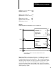
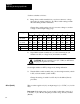
This example is written for the following conditions (Figure 4.2).
The module resides in rack 1, module group 2, slot 0 8-word block
transfer
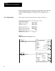
PLC2 Family Example