
User guide

Installing the Analog Input Module
Chapter 3
36
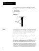
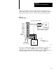
Figure 3.3
Power
Supply Connections (cat. no. 1770P1)
Jumper Positions
For 120V AC
L2
L1
+ 5V DC
+ 5V DC Common
Jumper Both Commons
- 15V DC
+ 15V DC
15V DC Common
-
+
14167
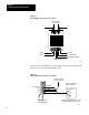
If you use the 1778-P2 remote power supply, connect it to the wiring arm
using one or two power cables (Figure 3.4).
Figure 3.4
Power
Supply Connections (cat. no. 1778P2)
12
11
10
9
8
7
Violet
Yellow
Black or Orange
Interlock
I/O
I/O
DC Common
+ 15V
- 15V
+ 5V
Field Wiring Arm for
Analog Input Module
Wiring for power cable (cat. no. 1770CF
is described in publication 17702.25)
Remote Power Supply
(Cat. No. 1778P2)
Analog Power able
(Cat. No. 1770CF)
Red or Blue
14166