
User guide

Installing the Analog Input Module
Chapter 3
32
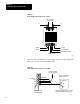
Touch a grounded object to rid yourself of elctrostatic charge before
handling the module.
Handle the module from the front, away from the backplane connector.
Do not touch backplane connector pins.
When setting internal switches or configuration plugs, do not touch
semiconductor devices inside the module. Use a static-safe work
station if available.
Keep the module in its static-shield bag when not in use.
CAUTION: Electrostatic discharge can degrade performance
or cause permanent damage. Handle this module as stated
above.
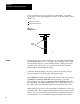
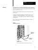
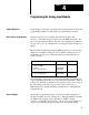
Your module requires 400 mA from the I/O chassis backplane. Calculate
the power usage of all modules in the I/O chassis so you do not exceed the
power rating of the chassis backplane or the backplane power supply.
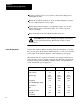
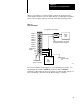
The input module also requires an external power supply exclusively for
analog modules. Using a separate supply protects the analog signal from
transients caused by the switching of digital circuits. The specifications
for the external DC power supply are:
Specifications 5V 15V 15V
current
per input module
150mA 70mA 70mA
voltage tolerance
1% 1% 1%
regulation (type)
linear
(series or
shunt)
linear
(series or
shunt)
linear
(series or
shunt)
line regulation
(for 10 VAC RMS input change)
.02% .02% .02%
load regulation
.04% .02% .02%
ripple
1 mV 1 mV 1 mV
overvoltage protection
7 V
18 V
18 V
current limit
(% of full load)
125% 125% 125%
Power Requirements