Allen Bradley Analog Input Module (Cat. No.
Table of Contents Using This Manual . . . . . . . . . . . . . . . . . . . . . . . . . . . . . . . 1 1 Chapter Objective . . . . . . . . . . . . . . . . . . . . . . . . . . . . . . . . . . . Purpose of This Manual . . . . . . . . . . . . . . . . . . . . . . . . . . . . . . . Audience . . . . . . . . . . . . . . . . . . . . . . . . . . . . . . . . . . . . . . . . . . Warnings and Cautions . . . . . . . . . . . . . . . . . . . . . . . . . . . . . . . Related Publications . . . . . . . . . . . . . . . . . .
ii Table of Contents Calibrating the Analog Input Module . . . . . . . . . . . . . . . . . 5 1 Chapter Objective . . . . . . . . . . . . . . . . . . . . . . . . . . . . . . . . . . . Service Information . . . . . . . . . . . . . . . . . . . . . . . . . . . . . . . . . . Calibration Equipment . . . . . . . . . . . . . . . . . . . . . . . . . . . . . . . . Before You Calibrate . . . . . . . . . . . . . . . . . . . . . . . . . . . . . . . . . Calibrating the Input Module . . . . . . . . . . . . . . . . . .
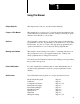
Chapter 1 Using This Manual Chapter Objective This chapter tells you how to use this manual efficiently. Purpose of This Manual This manual shows you how to use your 8-bit Analog Input Module with an Allen-Bradley programmable controller. It helps you install, program, calibrate, and troubleshoot your module. Audience We assume that you know how to program and operate an Allen-Bradley programmable controller. In particular, you should know how to program block transfer.
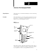
Chapter 2 Overview of the Analog Input Module Chapter Objectives This chapter gives you a functional and hardware overview of the analog input module. Description The module (Figure 2.1) senses analog signals at its inputs and converts these signals to 3-digit Binary Coded Decimal (BCD) values (0 to 255 BCD) for use by your programmable controller. Figure 2.
Chapter 2 Overview of the Analog Input Module manipulate values representing temperature, pressure, rotational speed, light intensity, and position. A wiring arm (cat. no. 1771-WB) accompanies the module. It acts as a terminal strip for input connections. The wiring arm pivots on the I/O chassis to connect with terminals on the front of the input module. Thus, the wiring arm lets you quickly connect or disconnect your input wiring when inserting or removing the input module from the I/O chassis.
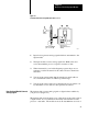
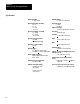
Chapter 2 Overview of the Analog Input Module Figure 2.2 Communication Between Input Module and Processor 2 4 1 Input Device 5 3 BTR 8- BIT Input Module (cat. no. 1771-IE) How the Input Module Converts Analog Signals PC Processor (PLC 2/30 Processor Shown) 14164 1. Input devices generate analog signals which are transmitted to the input module. 2. The input module converts analog signals into BCD values and stores them until the processor requests a transfer of data. 3.
Chapter 2 Overview of the Analog Input Module each input scan for formatting data, and cannot accept block transfers during this time. Figure 2.
Chapter 2 Overview of the Analog Input Module Figure 2.
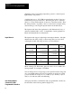
Chapter 2 Overview of the Analog Input Module Specifications Inputs Per Module 8 single ended Humidity Rating 5 to 95% (non condensing) Input Voltage Ranges (nominal) 1 to 5 V 0 to 5 V 0 to 10 V 10 to 10 V Keying (between) 4 and 6 26 and 28 A/D Converter Type successive approximation, monotonic Input Current Ranges (nominal) 0 to 20 mA 4 to 20 mA 20 to 20 mA Resolution 1 part in 256 (28) Linearity + 0.
Chapter 3 Installing the Analog Input Module Chapter Objectives This chapter gives you information on: choosing an external power supply wiring the input module’s field wiring arm keying a chassis slot for your module setting internal configuration switches installing the input module Before You Install the Input Module The input module is shipped to you configured for block transfer operation. If you want to use single transfer, see Appendix C for proper switch settings.
Chapter 3 Installing the Analog Input Module Touch a grounded object to rid yourself of elctrostatic charge before handling the module. Handle the module from the front, away from the backplane connector. Do not touch backplane connector pins. When setting internal switches or configuration plugs, do not touch semiconductor devices inside the module. Use a static-safe work station if available. Keep the module in its static-shield bag when not in use.
Chapter 3 Installing the Analog Input Module We recommend either of two Allen-Bradley power supplies: Power Supply (cat. no. 1770-P1) provides sufficient current for two 1771-IE input modules. This supply operates on either 120 or 220/240 VAC. The Remote Power Supply (cat. no. 1778-P2) provides external power for up to ten 1771-IE input modules. Do not use this supply for I/O chassis power when powering analog modules. We recommend that you order one or two power cables (cat. no.
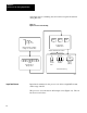
Chapter 3 Installing the Analog Input Module To key a module slot to accept only the 1771-IE module, position the keying bands on the upper backplane connector at the following positions (Figure 3.1): between 4 and 6 between 26 and 28 Figure 3.1 Keying Positions Keying Bands 2 4 6 8 10 12 14 16 18 20 22 24 26 28 30 32 34 36 14169 Wiring Connect analog devices and external power to your input module through the Field Wiring Arm (cat. no. 1771-WB).
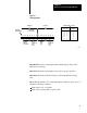
Chapter 3 Installing the Analog Input Module There is no restriction on cable length for current mode input devices. Cable length resistance, however, when added to module input resistance, must not be enough to cause an overload on the analog driving device. Figure 3.2 Connection Diagram (See application codes and laws.) Channel 1 1 Channel 2 2 Channel 3 3 Channel 4 4 Channel 5 5 Channel 6 6 Channel 7 7 Channel 8 Supply Comm/ Sig. Rtn.
Chapter 3 Installing the Analog Input Module Figure 3.3 Power Supply Connections (cat. no. 1770 P1) Jumper Positions For 120V AC L1 L2 + 5V DC - 15V DC + 5V DC Common + 15V DC Jumper Both Commons -+ 15V DC Common 14167 If you use the 1778-P2 remote power supply, connect it to the wiring arm using one or two power cables (Figure 3.4). Figure 3.4 Power Supply Connections (cat. no. 1778 P2) Analog Power able (Cat. No.
Chapter 3 Installing the Analog Input Module Grounding Ground the drain wire and shield of the Belden No. 8761 or equivalent cable (Figure 3.5) at one end of the cable only. Twist the drain wire and shield into a single strand. The best ground for this connection is an I/O chassis mounting bolt or stud. Insulate the shield and drain wire at the other end of the cable using electrical tape. You may mount a separate terminal near the input module for DC COMMON and SIGNAL RETURN wires.
Chapter 3 Installing the Analog Input Module Setting Configuration Switches The module is set for block transfer operation andcalibrated at the factory for the voltage or current range that you ordered. CAUTION: Electrostatic discharge can degrade performance or cause permanent damage to the module. Follow the guidelines on electrostatic discharge located at the beginning of this chapter before handling the module.
Chapter 3 Installing the Analog Input Module 1. Turn off power to the I/O chassis. WARNING: Remove power from the 1771 I/O chassis backplane and wiring arm before removing or installing an I/O module. Failure to remove power from the backplane could cause injury or equipment damage due to possible unexpected operation. Failure to remove power from the backplane or wiring arm could cause module damage, degradation or performance, or injury. 2. Insert your module into the chassis.
Chapter 4 Programming the Analog Input Module Chapter Objectives In this chapter we describe a general block transfer program, and present a programming example for each family of programmable controllers. Block Transfer Programming Program your processor to transfer data from the module to the processor’s data table using a block transfer read (BTR) instruction. We give you programming examples.
Chapter 4 Programming the Analog Input Module between instructions. Do not copy these examples. They are for instructional purposes only. Figure 4.1 Example Read Only Block Transfer Program Rung 1 BLOCK XFER READ EN DATA ADDR: MODULE ADDR: BLOCK LENGTH: FILE: Rung 2 BTR DN FILE TO FILE MOVE COUNTER ADDR: POSITION: FILE LENGTH: FILE A: DN EN DN FILE R: RATE PER SCAN: Rung 1 This rung uses the BTR instruction to transfer data to the processor.
Chapter 4 Programming the Analog Input Module BTR data (control) address is 030 BTR file address is 050 FFM counter address is 043 FFM number of words moved is 8 FFM source file A is 050 FFM destination file R is 150 FFM rate per scan is 8 Figure 4.
Chapter 4 Programming the Analog Input Module This rung adds up to 0.13ms to the processor scan time so use it sparingly. Locate it at the beginning of your ladder program. This logic is not required for PLC-2 family remote systems or for any other processor family. PLC 3 Family Example This example is written for the following conditions (Figure 4.3).
Chapter 4 Programming the Analog Input Module PLC 5/15 Example This example is written for the following conditions (Figure 4.4). The module resides in rack 1, module group 2, slot 0 8-word block transfer BT Array (integer control address) is $N7:51 Data file (integer file address) is $N7:56 Figure 4.
Chapter 4 Programming the Analog Input Module PLC 3 Family If your application requires many block transfer modules, distribute the modules over as many I/O chassis as possible to optimize transfer time for the system as a whole. Where allowed by your application, program block transfers to occur less often than once per program scan. Buffer incoming (BTR) data. Be sure it is valid before using it. Examine the BTR done bit and any other status bit that monitors its validity.
Chapter 5 Calibrating the Analog Input Module Chapter Objective This chapter describes how you calibrate the module. Service Information Your input module is calibrated at the factory. We recommend that you recalibrate it every year to maintain accuracy. If for some reason you can not calibrate the module, return it to Allen-Bradley Company for recalibration.
Chapter 5 Calibrating the Analog Input Module Before You Calibrate Before you calibrate, follow these steps: 1. Turn OFF power to the I/O chassis backplane and to your wiring arm. WARNING: Remove power from the 1771 I/O backplane and wiring arm before removing or installing an I/O module. Failure to remove power from the backplane could cause injury or equipment damage due to unexpected operation.
Chapter 5 Calibrating the Analog Input Module set internal switches adjust the offset (Part A) adjust the offset (Part B) calibrate the gain Setting the Switches There are three sets of switch assemblies (Figure 5.1) in the module: Range Select Signal Mode Transfer Mode Figure 5.
Chapter 5 Calibrating the Analog Input Module Set these switches as follows: 1. Range Select switch assembly lets you select a current or voltage input range by setting switches 1-10. These switch settings remain the same during and after calibration. Change these switch settings only if you want to change to another voltage or current input range group.
Chapter 5 Calibrating the Analog Input Module Make this adjustment for channel 1, only. 1. Set switch number 2 ON of the transfer mode switch assembly. 2. Place the module back in its I/O slot, and connect the wiring arm. 3. Change the processor mode select switch to test or program mode. Turn on power to the processor, I/O chassis, and external power supply to the module. 4. Connect the precision voltage source: positive lead to input channel 1 negative lead to DC COMMON of the wiring arm 5.
Chapter 5 Calibrating the Analog Input Module Figure 5.2 Location of Potentiometers and Test Points Potentiometer #1 Potentiometer #2 Potentiometer #3 Red Test Point Black Test Point 14163 8. Seal the setting with a drop of sealant. 9. Turn off power to the external power supply, I/O chassis, and processor. 10. Remove the module from the I/O chassis. 11. Reset switch number 2 OFF of the transfer mode switch assembly. 12.
Chapter 5 Calibrating the Analog Input Module 1. Jumper all 8 input terminals together at the wiring arm. 2. Connect the precision voltage source to the jumpered input terminals and to ground. 3. Set the precision voltage source to the input value required for minimum output for your particular input range. Remember that you set the module to operate in voltage mode for calibration. 4. Range Input for Minimum Output 1 to 5 V 1.0078 V 0 to 5 V 0.0098 V 10 to 10 V 9.9609 V 0 to 10 V 0.
Chapter 5 Calibrating the Analog Input Module 9. If your input range was a current range, reset the signal mode switch assembly to current mode (all switches on). 10. Re-install and test the module with known values before operating with I/O devices.
Appendix A Block Transfer (Multiple GET) for PLC 2/20 Example Program This read-only program (Figure A.1) transfers a block of input data from the analog input module to a momentary storage (buffer) in the processor’s data table. If valid, input data is moved elsewhere in the data table for use by your ladder program. If invalid, it is written over by the next block transfer. This program performs the same function as the 2-rung program described in chapter 4.
Appendix A Block Transfer (Multiple GET) for PLC-2/20 Figure A.
Appendix A Block Transfer (Multiple GET) for PLC-2/20 Description Scan 1 Rung 9 This rung controls block transfer. Preconditions are optional. The first available word 030 in the timer/counter accumulated area stores module location 120. Word 130 in the timer/counter preset area stores the address of the first word in the BTR (buffer) file. Output bit 01207 initiates block transfer. The first digit of this output address is zero, because it is in the output image table.
Appendix A Block Transfer (Multiple GET) for PLC-2/20 Rungs 11 18 These rungs move data from the BTR read file to storage. When the block transfer one-shot (02002) is set, data in each (buffer) word address 050-057 is moved to storage location 150-157 where it can be used by your ladder program. If data is not moved, it is written over by the next block transfer.
Appendix B Single Channel Transfer for PLC Processors Example Program Programming techniques used in this example program (Figure B.1) for the PLC processor include: I/O scan counter conditional ignore zone I/O Scan Counter The I/O scan counter (rungs 1-3) controls the transfer sequence and gives the module sufficient time to respond to channel byte and update select commands. The scan counter increments only when a program scan and I/O scan have occurred.
Appendix B Single Channel Transfer for PLC Processor The rungs within the conditional ignore zone (rungs 6-25) reconstruct and store the 16-bit input word from each channel. The override condition of the zone must be true (I/O scan counter accumulated value = 007) for the state of any output within the zone to be changed.
Appendix B Single Channel Transfer for PLC Processor Figure B.1 Example Program for the PLC Processor Rung No.
Appendix B Single Channel Transfer for PLC Processor 17 18 19 20 21 22 23 24 02002 01000 01001 01002 02002 02002 02002 02002 02002 02002 02002 01000 250 G 000 01001 250 G 000 01002 250 G 000 01003 250 G 000 01004 250 G 000 01005 250 G 000 01006 250 G 000 25 26 27 28 29 30 31 B 4 200 G 000 200 G 000 367 = 007 367 = 007 200 G 000 203 G 000 200 G 000 367 = 007 361 = 001 363 < 003 203 G 000 200 G 000 203 G 000 362 = 002 363 < 003 363 = 003 01003 01004 01005 01006 250 G 000 260
Appendix B Single Channel Transfer for PLC Processor 32 33 34 35 36 203 G 000 203 G 000 364 = 004 365 = 005 01003 203 G 000 366 = 006 01005 203 G 000 203 G 000 367 = 007 370 = 008 01006 01004 200 CTR 02200 37 38 203 G 000 260 G 000 Channel SELECT Bits Reset Counters 370 = 008 261 G 000 203 CTR 262 G 000 263 G 000 264 G 000 265 G 000 266 G 000 267 G 000 END 0400 Display Rung B 5
Appendix B Single Channel Transfer for PLC Processor Program Logic In single channel transfer, the processor transfers data one byte at a time. Your program must reconstruct the data into 16-bit words in the correct sequence. We developed a flow chart (Figure B.2) that describes single transfer programming to help you understand the logic. Figure B.2 Flow Chart for PLC Example Program Rung No. 1-3 Rung No. Start Yes Is Scan count = 7? Increment I/O scan counter (200) 6 No 1.
Appendix B Single Channel Transfer for PLC Processor Assumptions The example program is based on the following assumptions: The input module is in slot 0 of module group 0 in rack 1. All eight channels are used. If fewer channels are used, rungs may be eliminated.
Index A audience, 1 1 L Location of module, 3 3 Location of potentiometers, 5 6 C Calibration equipment, 5 1 Calibration procedure, 5 2 gain, 5 7 offset (part A), 5 4 offset (part B), 5 6 Communication, module to processor, 2 3 configuraion switches, 3 8 Connection Diagram, 3 5 E Location of switch assemblies, 5 3 P Power requirements, 3 2 Power supply connections, 3 6 Programming block transfer, 4 1 general example, 4 1 PLC-2 family example, 4 2 PLC-2/20 (using multiple GET), A 1 PLC-3 family example
Allen Bradley, a Rockwell Automation Business, has been helping its customers improve pro ductivity and quality for more than 90 years. We design, manufacture and support a broad range of automation products worldwide. They include logic processors, power and motion control devices, operator interfaces, sensors and a variety of software. Rockwell is one of the worlds leading technology companies. Worldwide representation.