
Installation Instructions Manual


ac (120V) Isolated Input Module 7
Publication 1771-IN001A–EN–P – May 2000
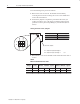
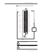
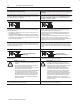
Figure 1
Connection Diagram for the 1771-ID16GM ac (120V) Isolated Input
Module
Input 0
Input 1
Input 2
Input 3
Input 4
Input 5
Input 6
Input 7
Input 10
Input 11
Input 12
Input 13
Input 14
Input 15
Input 16
Input 17
L2
ac High
ac Low
L2 - 0
L2 - 1
L2 - 2
L2 - 3
L2 - 4
L2 - 5
L2 - 6
L2 - 7
L2 - 10
L2 - 11
L2 - 12
L2 - 13
L2 - 14
L2 - 15
L2 - 16
L2 - 17
Not Used
Not used
Not used
Not used
Not used
Not used
Not used
Not used
120V ac
Supply
L2
L1
2
4
6
8
10
12
14
16
18
20
22
24
26
28
30
32
34
36
38
40
(Actual wiring runs in this direction.)
ac Low
ac Input
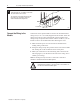
!
ATTENTION: Maintain isolation between phases to
prevent module damage.
!
ATTENTION: Do not use any 1771 ac output
modules to drive the 1771-ID16GM input module.