
Installation Instructions Manual
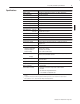

Specifications
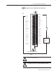
ac (120V) Isolated Input Module 11
Publication 1771-IN001A–EN–P – May 2000
Inputs per Module 16
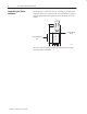
Module Location 1771-A1B thru -A4B or later I/O chassis; 1771-AM1, -AM2 chassis
Input Voltage Range 105–120V ac, 47-63Hz
Nominal Input Voltage 120V ac
Nominal Input Current 2.5mA ac
On State Voltage (minimum) 105V ac
On State Current (minimum) 2.0mA @ 105V ac
Off State Voltage (maximum) 45V ac
Off State Current (maximum) 0.8mA @ 45V ac
Input Signal Delay Off to On
On to Off
0.57ms
Selectable: 9ms or 18.0ms
Input Impedance (minimum) 75Kohms off, 48Kohms on
Power Dissipation 7.0 Watts (max.), 0.3 Watts (min.)
Thermal Dissipation 23.8 BTU/hr (max.), 1.0 BTU/hr (min.)
Backplane Current 75mA maximum
Tested Isolation Voltage Tested to 1500V ac channel-to-channel for 1s; 1500V ac channel to
backplane for 1s
Maximum Cable Length 1000ft (304.8m)
Environmental Conditions
Operational Temperature
Storage Temperature
Relative Humidity
0
o
to 60
o
C (32
o
to 140
o
F)
-40
o
to 85
o
C (-40
o
to 185
o
F)
5 to 95% (without condensation)
Conductors Wire Size
Category
14 to 22 gauge (2.5mm
2
to 0.25mm
2
) stranded or solid copper only
1,2
3/64 inch (1.2mm) insulation maximum
1
3
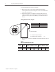
Keying Between 22 and 24
Between 26 and 28
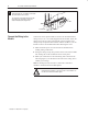
Wiring Arm Catalog Number 1771-WN
Wiring Arm Screw Torque 9 pound-inches (1.0Nm)
Agency Certification
(when product is marked)
• CSA certified
• CSA Class 1, Division 2, Groups A, B, C and D certified
• UL listed
• CE marked for all applicable directives
• C-Tick marked for all applicable acts
1
One or two 14–22 AWG solid or stranded copper wires per terminal. Must be same size. Do not intermix solid and stranded wires. Use copper
wire only.
2
14 gauge wire connected to all terminals may not allow the field wiring arm cover to close. A smaller wire size may be required.
3
Refer to publication 1770-4.1, “Industrial Automation Wiring and Grounding Guidelines.”