
Install Instr ac/dc (120V)Isolated Input User guide


ac/dc (120V) Isolated Input Module 7
Publication 1771-IN070B-EN-P - August 2002
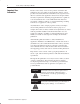
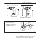
Swing the chassis locking bar down into place to secure
the modules. Make sure the locking pins engage.
1771ĆA1B, ĆA2B, ĆA3B, ĆA3B1, ĆA4B I/O chassis
1771ĆA1B, ĆA2B, ĆA3B1, ĆA4B Series B I/O chassis
locking tab
card guides
Module
Module
19809
card guides
locking bar
locking bar pin
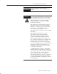
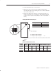
Snap the chassis latch over
the top of the module to secure it.
17643
wiring arm
remove
horizontal bar
Attach the wiring arm (1771ĆWN) to the horizontal
bar at the bottom of the I/O chassis.
The wiring arm pivots upward and connects with
the module so you can install or remove the
module without disconnecting the wires.
1771ĆWN
The 1771–ID16/B module is a modular component of the 1771 I/O
system requiring a properly installed system chassis. Refer to
publication 1771–IN075 for detailed information on acceptable
chassis, proper installation and grounding requirements. Limit the
maximum adjacent slot power dissipation to 10W maximum.