Installation Instructions DC (10...
DC (10...30V) Input Module Important User Information Solid state equipment has operational characteristics differing from those of electromechanical equipment. Safety Guidelines for the Application, Installation and Maintenance of Solid State Controls Publication SGI-IN001 available from your local Rockwell Automation sales office or online at http://literature.rockwellautomation.com) describes some important differences between solid state equipment and hard-wired electromechanical devices.
DC (10...30V) Input Module 3 Environment and Enclosure ATTENTION This equipment is intended for use in a Pollution Degree 2 industrial environment, in overvoltage Category II applications (as defined in IEC publication 60664-1), at altitudes up to 2000 m (6562 ft) without derating. This equipment is considered Group 1, Class A industrial equipment according to IEC/CISPR Publication 11.
DC (10...30V) Input Module European Hazardous Location Approval ATTENTION This equipment is intended for use in potentially explosive atmospheres as defined by European Union Directive 94/9/EC and has been found to comply with the Essential Health and Safety Requirements relating to the design and construction of Category 3 equipment intended for use in potentially explosive atmospheres, given in Annex II to this Directive.
DC (10...30V) Input Module 5 North American Hazardous Location Approval The following information applies when operating this equipment in hazardous locations. Informations sur l’utilisation de cet équipement en environnements dangereux. Products marked "CL I, DIV 2, GP A, B, C, D" are suitable for use in Class I Division 2 Groups A, B, C, D, Hazardous Locations and nonhazardous locations only.
DC (10...30V) Input Module Before You Begin The 1771-IBN series C DC input module is a sink input and requires a source output. A sink input provides a path to ground and a source output provides a positive voltage path. You must use this module in a 1771-A1B through 1771-A4B or later 1771 I/O chassis. Refer to the table for processor compatibility. Processor Capability System Type Use with Processors Cat. No.
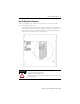
DC (10...30V) Input Module 7 Key the Backplane Connector Place your module in any slot in the chassis except the leftmost slot that is reserved for processors or adapters, noting that you: • should position the keying bands in the backplane connectors to correspond to key slots on the module so that you place the keying bands between 14…16 and 18…20. • can change the position of these bands if subsequent system design and rewiring makes insertion of a different type of module necessary.
DC (10...30V) Input Module Install the Module and Field Wiring Arm The 1771–IBN module is a modular component of the 1771 I/O system requiring a properly installed system chassis. Refer to Universal I/O Chassis Installation Instructions publication 1771-IN075 for detailed information on acceptable chassis and proper installation and grounding requirements. Limit the adjacent slot-power dissipation to 10 W maximum.
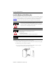
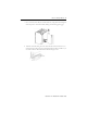
DC (10...30V) Input Module 9 • For a 1771-A1B, 1771-A2B, 1771-A4B I/O chassis, swing the chassis locking bar down into place to secure the modules, making sure the locking pins engage. 2. Attach the 1771-WN wiring arm to the horizontal bar at the bottom of the I/O chassis noting the wiring arm pivots upward and connects with the module so you can install or remove the module without disconnecting the wires.
DC (10...30V) Input Module Connecting Wiring to the Field Wiring Arm You make connections to the module through the 1771-WN field wiring arm. The arm pivots on the I/O chassis to connect with terminals on the front of the module and acts as a terminal strip. The wiring arm allows the module to be removed from the chassis without disconnecting wiring. WARNING WARNING ATTENTION The optional 1771-WHF and 1771-WHFB fused field-wiring arms are not certified for use in hazardous location applications.
DC (10...30V) Input Module 11 I/O Module Groups Each module condenses two full-module groups (32 inputs) into each I/O chassis slot. For example: • module group 1 = inputs 00…17. • module group 2 = inputs 00…17 (module group 2 represents the second set of inputs). ATTENTION Observe proper polarity with DC power connections. Reverse polarity or application of AC voltage could damage the module.
DC (10...
DC (10...
DC (10...
DC (10...30V) Input Module 15 Status Indicators The module has 32 status indicators on the front plate. These represent the control status of the input. Each indicator is lit when voltage is present at the corresponding input. These indicators can flicker (momentarily light up) when the chassis in which the module resides is first powered up. This flicker is normal and in no way affects the control parameters of the system.
DC (10...30V) Input Module Specifications DC (10…30V) Input Module Attribute Value Inputs per module 32 Module location 1771-A1B through 1771-A4B or later I/O chassis Input voltage range 10…30V DC Input range, nom 4.7 mA @ 10V; 15.6 mA @ 30V Off-state current, min 1.7 mA @ 5V DC Off-state voltage, max 5V DC On-state voltage, min 10V DC Input signal delay Low to high propagation: 6 ms +2 ms High to low propagation: 6 ms +2 ms Power dissipation 16.4 W max; 1.
DC (10...
DC (10...30V) Input Module Certifications(1) Certification(2) Value CSA CSA Certified Process Control Equipment. See CSA File LR54689C. CSA Certified Process Control Equipment for Class I, Division 2 Group A,B,C,D Hazardous Locations. See CSA File LR69960C. Ex European Union 94/9/EC ATEX Directive, compliant with: EN 60079-15; Potentially Explosive Atmospheres, Protection "n" (II 3 G Ex nA IIC T3 X) EN 60079-0; General Requirements (Zone 2).
DC (10...
Rockwell Automation Support Rockwell Automation provides technical information on the Web to assist you in using its products. At http://support.rockwellautomation.com, you can find technical manuals, a knowledge base of FAQs, technical and application notes, sample code and links to software service packs, and a MySupport feature that you can customize to make the best use of these tools.