Allen-Bradley BASIC Module Series B (Cat. No.
Important User Information Because of the variety of uses for the products described in this publication, those responsible for the application and use of this control equipment must satisfy themselves that all necessary steps have been taken to assure that each application and use meets all performance and safety requirements, including any applicable laws, regulations, codes and standards.
Preface A Summary of Changes What’s in This Preface? Read this preface if you are replacing a 1771-DB, Series A module with a 1771-DB, Series B module or are using the BASIC module for the first time.
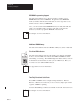
Preface A Summary of Changes EEPROM Programming Support The Series B module has two sockets for memory modules: one for EEPROM and the other for EPROM. Program and erase EEPROM memory modules with the Series B module. You no longer have to use CALLs 8 and 9 to burn your EEPROM. Also, you can read and run the EPROM memory module (8K, 16K, and 32K) you programmed with your Series A module on the Series B. However, you cannot program an EPROM on the Series B. Chapter See Chapter 3 for more information.
Preface A Summary of Changes Error-Trapping Support The ONERR statement (page 11 -23) traps overflow, underflow, and divide-by-zero errors in the Series B module. Also, the Series B offers expanded error (CALL 38, page 12 -36) support for non-hardware errors undefined in the ONERR statement. DH-485 Network Support The Series B module has a DH485 port that you can use as a network port or a programming port. Chapter See Chapter 2 for more information.
Preface A Summary of Changes Turbo Speed Allows Faster Program Execution The BASIC module operates up to four times faster than before. With a C toolkit and C compiler available from one of our Pyramid Solutions Program partners, you can run C programs on the BASIC module even faster. See your Allen-Bradley representative for more details on the C toolkit. You can also run the BASIC module at the same speed as the Series A module for applications that cannot be run at a faster speed.
Preface A Summary of Changes Call Routine Changes and Additions These calls are new to the Series B, BASIC module: Statement CALL 0 CALL 14 CALL 15 CALL 16 CALL 18 CALL 19 CALL 24 CALL 25 CALL 29 CALL 49 CALL 50 CALL 83 CALL 84 CALL 85 CALL 86 CALL 87 CALL 88 CALL 89 CALL 90 CALL 91 CALL 92 CALL 93 CALL 94 CALL 95 CALL 96 CALL 97 CALL 98 CALL 100 CALL 101 CALL 103 CALL 104 CALL 105 CALL 108 CALL 112 CALL 113 CALL 114 CALL 115 CALL 116 CALL 117 CALL 118 CALL 120 CALL 122 CALL 123 Page reset the module SLC
Preface A Summary of Changes The definitions of these calls have changed: Important: The Series A definitions are not supported in the Series B.
Preface A Summary of Changes Changes to the Manual Since the Last Printing We have corrected these items that appeared in the previous version of this manual (1771-6.5.113; November 1994).
Preface A Summary of Changes Notes: SOC-8
Preface B Using This Manual What’s in This Preface? This introduction describes how to properly and efficiently use this manual. This introduction tells you: the purpose of this manual who should use this manual how to use this manual abbreviations and conventions related publications Allen-Bradley support publication 1771-6.5.113 Purpose of This Manual Use this manual as guide for the design, installation, and programming of the BASIC module (1771-DB, Series B).
Preface B Using This Manual How To Use This Manual This manual is designed so you can follow it to install your hardware and program your BASIC module.
Preface B Using This Manual Terms and Abbreviations Throughout this manual, we abbreviate some terms. The terms and abbreviations listed in this table are specific to this product. For a complete listing of Allen-Bradley terminology, refer to the Allen-Bradley Industrial Automation Glossary, (AG-7.1). Term/Abbreviation Definition ASCII port port used to connect to foreign devices.
Preface B Using This Manual Conventions We use these conventions in this manual: In this manual, we show: prompts and messages literal text that you type variable text that you type keys that you press that there is more information about the topic in another chapter in this manual Like this: Press a function key RUN filename F3 Chapter that there is more information about the topic in another manual helpful information Tip Bulleted lists provide information, not procedural steps.
Preface B Using This Manual Getting Started To install and program the BASIC module follow the flowchart below.
Preface B Using This Manual Allen-Bradley Support Allen-Bradley offers support services worldwide, with over 75 sales/support offices, 512 authorized distributors and 260 authorized systems integrators located throughout the United States alone. As well, Allen-Bradley has representatives in every major country in the world.
Table of Contents Installing the BASIC Module Chapter 1 What’s in This Chapter? . . . . . . . . . . . . . . . . . . . . . . . . . . . . . . . Guard Against Electrostatic Damage . . . . . . . . . . . . . . . . . . . . . Unpack the Module . . . . . . . . . . . . . . . . . . . . . . . . . . . . . . . . . . . Install Memory Module . . . . . . . . . . . . . . . . . . . . . . . . . . . . . . . . Configure Jumpers . . . . . . . . . . . . . . . . . . . . . . . . . . . . . . . . . . . .
Table of Contents Programming Block-Transfers Chapter 5 Editing and Debugging a BASIC Program Chapter 6 Using BASIC Module Statements Chapter 7 Data Types Chapter 8 What’s in This Chapter? . . . . . . . . . . . . . . . . . . . . . . . . . . . . . . . 5-1 BASIC Module Memory Organization . . . . . . . . . . . . . . . . . . . . 5-1 Data Tables . . . . . . . . . . . . . . . . . . . . . . . . . . . . . . . . . . . . . . . . . 5-2 Block-Transfer Buffers . . . . . . . . . . . . . . . . . . . . . . . . .
Table of Contents Expressions, Variables and Operators Chapter 9 Commands Chapter 10 What’s in This Chapter? . . . . . . . . . . . . . . . . . . . . . . . . . . . . . . . Expressions . . . . . . . . . . . . . . . . . . . . . . . . . . . . . . . . . . . . . . . . . Relational Expressions . . . . . . . . . . . . . . . . . . . . . . . . . . . . . . . . Constants . . . . . . . . . . . . . . . . . . . . . . . . . . . . . . . . . . . . . . . . . . . Variables . . . . . . . . . . . . . . . . . . . . . . . . .
Table of Contents Statements Chapter 11 What’s in This Chapter? . . . . . . . . . . . . . . . . . . . . . . . . . . . . . . . CLEAR . . . . . . . . . . . . . . . . . . . . . . . . . . . . . . . . . . . . . . . . . . . . CLEARI . . . . . . . . . . . . . . . . . . . . . . . . . . . . . . . . . . . . . . . . . . . . CLEARS . . . . . . . . . . . . . . . . . . . . . . . . . . . . . . . . . . . . . . . . . . . CLOCK0 . . . . . . . . . . . . . . . . . . . . . . . . . . . . . . . . . . . . . . . . . . . CLOCK1 .
Table of Contents Call Routines 0 - 68 Chapter 12 What’s in This Chapter? . . . . . . . . . . . . . . . . . . . . . . . . . . . . . . . CALL 0: Reset Module . . . . . . . . . . . . . . . . . . . . . . . . . . . . . CALL 2: Timed Block- Transfer-Read Buffer . . . . . . . . . . . . CALL 3: Timed Block- Transfer-Write Buffer . . . . . . . . . . . CALL 4: Set Block- Transfer-Write Length . . . . . . . . . . . . . CALL 5: Set Block- Transfer-Read Length . . . . . . . . . . . . .
Table of Contents CALL 39: 3.3-Digit Signed, Fixed Decimal BCD to BASIC Floating Point . . . . . . . . . . . . . . . . . . . . . . . CALL 40: Set the Wall Clock Time (Hour, Minute, Second) . CALL 41: Set Wall Clock Date (Day, Month, Year) . . . . . . . . CALL 42: Set Wall Clock Day of Week . . . . . . . . . . . . . . . . . CALL 43: Retrieve Date/Time String . . . . . . . . . . . . . . . . . . CALL 44: Retrieve Date Numeric (Day, Month, Year) . . . . . CALL 45: Retrieve Time String . . . . . . . . . . . .
Table of Contents CALL 90: CALL 91: CALL 92: CALL 93: CALL 94: CALL 95: CALL 96: CALL 97: CALL 98: CALL 99: CALL 100: CALL 101: CALL 103: CALL 104: CALL 105: CALL 108: CALL 109: CALL 110: CALL 111: CALL 112: CALL 113: CALL 114: CALL 115: CALL 116: CALL 117: CALL 118: CALL 119: CALL 120: CALL 122: CALL 123: Read Remote DH-485 Data File to BASIC Input Buffer . . . . . . . . . . . . . . . . . . . . . . . . 13-18 Write BASIC Output Buffer to Remote DH-485 Data File . . . . . . . . . . . . . . . . . . .
Table of Contents Product Overview Appendix A What’s in This Appendix? . . . . . . . . . . . . . . . . . . . . . . . . . . . . . . A-1 Features . . . . . . . . . . . . . . . . . . . . . . . . . . . . . . . . . . . . . . . . . . . . A-1 Programming Interfaces . . . . . . . . . . . . . . . . . . . . . . . . . . . . . . . A-5 Network Configurations . . . . . . . . . . . . . . . . . . . . . . . . . . . . . . . A-7 Memory Requirements . . . . . . . . . . . . . . . . . . . . . . . . . . . . . . . .
Chapter 1 Installing the BASIC Module What’s in This Chapter? Guard Against Electrostatic Damage This chapter describes: On page: guard against electrostatic discharge unpack the module calculate power requirements install memory module configure the jumpers determine BASIC module placement key the backplane connector install module in the I/O chassis connect peripheral devices power up the module reset the module read the indicator lights what’s next? 1 -1 1 -2 1 -2 1 -2 1 -3 1 -10 1 -11 1 -12 1 -1
Chapter 1 Installing the BASIC Module Unpack the Module Verify all the items in your package against the packing sheet. If any of the items are missing or incorrect, contact your local Allen-Bradley sales office. BASIC Module (Cat. No. 1771-DB) User Manual Important: Save packing materials in case you need to return an item for servicing. Calculate Power Requirements The BASIC module receives its power through the 1771 I/O chassis backplane from the chassis power supply.
Chapter 1 Installing the BASIC Module Configure the Jumpers The BASIC module has nine sets of jumpers that you need to set. For future reference, place a ✔ next to the jumper setting you choose in the “Your Selection” column of the tables to follow.
Chapter 1 Installing the BASIC Module Set Watchdog Timer Enable Jumper (JW1) Use JW1 to enable the watchdog timer. Unless you are using assembly language code that you programmed for your Series A module, you should enable this jumper. To: ✔ your selection: Set jumper : enable the watchdog timer factory setting disable the watchdog timer Set Memory Module Configuration Jumper (JW2) Use JW2 to configure your non-volatile memory.
Chapter 1 Installing the BASIC Module Set CPU Speed Select Jumper (JW3) Chapter Use JW3 to select the operating speed of your BASIC module processor. Unless you are using a memory module that is slower than 90 ns, set this jumper to turbo to obtain optimum performance. Memory modules that are slower than 90 ns are too slow to run in turbo; you must set the jumper to normal. Refer to Chapter 3 for more information on memory modules.
Chapter 1 Installing the BASIC Module Set Operating Mode Jumper (JW4) Chapter Use JW4 to configure your communication ports as a program port, ASCII port, network port, or DF1 protocol. Also configure your power on operating condition. Refer to Chapter 2 for more information regarding the operation mode.
Chapter 1 Installing the BASIC Module Set Backplane Configuration (JW5) Use JW5 to set the BASIC module backplane configuration. The BASIC module can perform both block and discrete transfers. With JW5 set to 8-point mode, the BASIC module uses 8 bits in both the input and output image table for block transfer. When you have JW5 (page 1 -7) configured for 16-point mode, the firmware also allows you to examine/use bits 10–17 for status of the communication ports.
Chapter 1 Installing the BASIC Module Set PRT2 Communication Rate Select Jumper (JW6) Use JW6 to set the communication rate for PRT2 at power-up. Set the communication rate according to your application. Important: You can also select the communication rate for PRT2 within your program. The settings you select with PROG1 (page 10 -12) and PROG2 (page 10 -13) override the jumper setting until the module is powered down.
Chapter 1 Installing the BASIC Module Set Battery Enable Jumper (JW7) Use JW7 to enable the battery. To conserve the battery, your module is shipped with the battery disabled. When the BASIC module is in use, you should enable the battery. If you do not enable the battery, your program is not backed up if a power failure occurs.
Chapter 1 Installing the BASIC Module Determine BASIC Module Placement You install the BASIC module in a 1771-I/O chassis. You can place your module in any slot of the I/O chassis except for the extreme left slot (his slot is reserved for processors or adapter modules). We recommend that you remember these points: When selecting slots for modules, always try to group modules to minimize adverse effects from electrical noise and radiated heat.
Chapter 1 Installing the BASIC Module Key the Backplane Connector Use the plastic keying clips shipped with each I/O chassis to key the I/O slot to accept only a BASIC module. The BASIC module is slotted in two places on the rear edge of the circuit board. The position of the keys on the backplane connector must correspond to these slots to allow insertion of the module. Snap the keys onto the upper backplane connectors between 8 and 10 and between 32 and 34.
Chapter 1 Installing the BASIC Module Install the Module into the 1771 I/O Chassis You are now ready to install the module into the I/O chassis. ATTENTION: Disconnect and lockout all power from the programmable controller and system power supplies before installing modules to avoid injury to personnel and damage to equipment. 1. Turn off power to the I/O chassis. 2. Use the card guides on the top and bottom of the slot to place the BASIC module into position.
Chapter 1 Installing the BASIC Module Connect Peripheral Devices Chapter Now that you have installed your BASIC module into the I/O rack, you need to connect your external devices to the communication ports. See Chapter 2 for cable pin out information. 20376–M Power up the Module Apply power to your I/O chassis backplane. At power up, the top six LEDs are on. They go off one at a time as each part of the module self-test successfully passes.
Chapter 1 Installing the BASIC Module Read the Indicator Lights The BASIC module has 10 indicator LEDs: This LED: Indicates: the module mode and whether the BASIC module is receiving power from the backplane whether a system problem was detected during background diagnostics whether port DH485 on the BASIC module is active for communication whether the voltage of the battery that backs up RAM is low User definable. LED activated through the user program. User definable.
Chapter 2 Using the Communication Ports What’s in This Chapter? Communication Ports Overview This chapter describes: On page: communication ports overview communication modes handshaking communication rates operating modes what’s next? 2 -1 2 -2 2 -4 2 -6 2 -7 2 -13 The BASIC module has three communication ports: DH485, PRT2, and PRT1. Through the configuration you select, you can designate at least one of these ports to function as a program port, ASCII port, network port, or DF1 protocol port.
Chapter 2 Using the Communication Ports Communication Modes PRT1 and PRT2 Port You can configure ports PRT1 and PRT2 for these communication modes: RS-232C – communicate with a RS-232 device or an unterminated RS-423 device within 50 ft. RS-422 – point to point and multidrop for RXD/TXD connections RS-485 – multidrop supported for RXD/TXD connections The communication mode you choose depends on the device you are connecting to the BASIC module. Refer to the documentation accompanying the device.
Chapter 2 Using the Communication Ports PRT1 and PRT2 Transmit and Receive Buffers Ports PRT1 and PRT2 each have a 256-character receive (input) buffer and a 256-character transmit (output) buffer. Data in these buffers are monitored by circular queues. If a queue detects that a buffer is full (i.e.
Chapter 2 Using the Communication Ports Handshaking The BASIC module support both hardware and software handshaking. You turn hardware and software handshaking on and off through the MODE statement (page 11 -20). Software Handshaking The BASIC module uses these rules when software handshaking is enabled: When the BASIC module receives an XOFF from the external device, it is recognized immediately and the BASIC module stops sending characters from the transmit buffer to the UART.
Chapter 2 Using the Communication Ports Hardware Handshaking The BASIC module uses these rules when hardware handshaking is enabled. The BASIC module: does not transmit until CTS, DCD, and DSR become active examines DSR and DCD following the receipt of a character. If the DSR and DCD are active, the character is placed in the input queue. If DSR or DCD is inactive, the character is assumed to be noise and is discarded.
Chapter 2 Using the Communication Ports Communication Rates You can operate PRT1 and PRT2 ports full-duplex and DH485 port half-duplex at 300, 600, 1200, 2400, 4800, 9600 or 19200 bit/s. You can set the communication rates for PRT1, PRT2, and DH485 ports using the MODE (page 11 -20) statement and store the settings using the PROG1 (page 10 -12) and PROG2 (page 10 -13) commands. You can set the communication rate for the program port with CALL 78 (page 13 -8).
Chapter 2 Using the Communication Ports Operating Modes Depending on how you set jumper JW4 (see Set Operating Mode, page 1 -6), you can configure: Port PRT1 as: ASCII port program port Port PRT2 as: ASCII port DF1 protocol port Port DH485 as: program port network port disabled 2 -7
Chapter 2 Using the Communication Ports JW4 ASCII Port Configurations PRT1 and PRT2 ASCII Only PRT2 ASCII Only PRT2 ASCII ASCII Port If you set JW4 to one of the configurations shown at the left, PRT1 and/or PRT2 are ASCII ports (asynchronous serial communication channels) compatible with RS-232C, RS-422, RS-485 interfaces. When you configure PRT1 and PRT2 as ASCII ports, you use jumpers JW8 and JW9 (page 1 -9) to select an electrical interface.
Chapter 2 Using the Communication Ports Program Port You can configure either PRT1 or DH485 as your program port. JW4 PRT1 Program Port Configurations (See chapter 1 for additional information on these settings.) PRT1 Configured as Program Port If you set JW4 to one of the configurations shown at the left, PRT1 is the program port. In this configuration, the serial port on the console device is connected to port PRT1 on the BASIC module.
Chapter 2 Using the Communication Ports DF1 Protocol JW4 DF1 Protocol Configuration If you set JW4 to the configuration shown at the left, PRT2 port can be configured via a BASIC program for DF1 protocol. The BASIC module uses DF1 protocol to communicate with external devices using, for example, a leased phone line, radio link or dial-up modem. Important: When DF1 protocol is selected on port PRT2, DH-485 communications are disabled.
Chapter 2 Using the Communication Ports JW4 DH485 Network Port Configuration (See chapter 1 for additional information on these settings.
Chapter 2 Using the Communication Ports 1747-PIC Interface/Converter/1747-AIC Isolated Link Coupler Use the 1747-PIC interface/converter to convert the RS-232 signals from the personal computer’s serial port to DH-485 format. This figure shows the interface/converter integrating a personal computer with the PBASE software to the BASIC module across a DH-485 network. The 1747-AIC isolated link coupler allows you to link modules to the DH-485 network.
Chapter 2 Using the Communication Ports 1747-AIC Link Coupler/1784-KR DH-485 Interface Card The 1784-KR DH-485 Interface Card enables your personal computer to communicate across the DH-485 network to the BASIC module without the interface/converter. This figure shows a DH-485 network configuration with the 1784-KR DH-485 Interface Card and its host computer linked with the BASIC module through a link coupler.
Chapter 2 Using the Communication Ports Notes: 2 -14
Chapter 3 Installing and Replacing Components What’s in This Chapter? Before You Begin Refer to this chapter if you are installing or replacing a memory module or the battery. If not, go on to Chapter 4, “Programming the BASIC Module”.
Chapter 3 Installing and Replacing Components Remove the BASIC Module from the I/O Chassis Before you can add or replace components, you must remove the module from the I/O chassis. Go to page 3 -3, if you already removed the BASIC module from the chassis. ATTENTION: Shut off power to the I/O chassis before removing the BASIC module; otherwise, personal injury or damage to equipment may result. To remove the BASIC module from the I/O chassis: 1.
Chapter 3 Installing and Replacing Components Disassemble the BASIC Module Before you can install the optional memory module or battery, you have to disassemble the BASIC module. ATTENTION: Electrostatic discharge can damage integrated circuits or semiconductors in the module of you touch backplane connector pins. Use a static-safe workstation, if available. 1. Remove the cover from the right side of the BASIC module. Important: Be careful not to lose the washers. 20369–M 2.
Chapter 3 Installing and Replacing Components Install Optional Memory Module The BASIC module supports these Allen-Bradley Memory Modules: 8K EEPROM (Cat. Nos. 1771-DBMEM1 or 1747-M1) 32K EEPROM (Cat. Nos. 1771-DBMEM2 or 1747-M2) 8K EPROM (Cat. No. 1747-M3) 32K EPROM (Cat. No. 1747-M4, PN 940654-02, or PN 940654-03) Also, you can use any JEDEC standard 8K, 16K, or 32K EPROM or 8K or 32K EEPROM with speeds faster than 150 ns (for example 90 ns).
Chapter 3 Installing and Replacing Components To install your optional memory module: Refer to this table when installing your memory module.
Chapter 3 Installing and Replacing Components 4. Place the board on a flat surface. SKT1 (PROMs with Carriers) SKT2 (PROMs without Carriers) 20371–M 5. Insert the memory module into the appropriate socket.
Chapter 3 Installing and Replacing Components Use a chip insertion tool with memory modules that have no carrier. SKT2 (PROMs without Carriers) Important: Make sure you line up the index mark on the PROM with the index mark on the socket. Important: Make sure that none of the pins on the PROM are bent and that all the pins are aligned in the socket correctly. Index Mark 20373–M 6. Reassemble the BASIC module. If you need further instructions to complete this step, see page 3 -11. 7.
Chapter 3 Installing and Replacing Components Install the Battery The battery backs up 24K bytes of user RAM and the clock/calendar. Drain on the battery should be less than 0.5 mA dc during battery back-up (no power) and less than 50 uA while the module is powered. Battery life during no-power conditions is about 2,000 hours. Battery shelf life is about 20,000 hours. When the BTLO LED indicator light comes on the battery should maintain the clock and program data for about three days.
Chapter 3 Installing and Replacing Components To replace the battery: 1. Remove the BASIC module from the I/O chassis. If you need further instructions to complete this step see page 3 -2. 2. Disassemble the BASIC module. If you need further instructions to complete this step, see page 3 -3. ATTENTION: Electrostatic discharge can damage integrated circuits or semiconductors in the module if you touch backplane connector pins.
Chapter 3 Installing and Replacing Components 4. Remove the battery and insert a fresh one. Make sure you install the battery in the correct orientation. + – 5. Replace the battery cover. 6. Reassemble the BASIC module. If you need further instructions to complete this step, see page 3 -11. 7. Make sure jumper JW7 is enabled (page 1 -9). 8. Replace the BASIC module into the I/O chassis. If you need further instructions to complete this step, see page 1 -12.
Chapter 3 Installing and Replacing Components Reassemble the BASIC Module After installing the memory module or battery, reassemble the BASIC module as follows: 1. Insert the board into the main case. 20370–M 2. Replace the right-side cover. Important: Make sure you replace the washers. Also, do not over-tighten the screws; otherwise you can damage the cover.
Chapter 3 Installing and Replacing Components Notes: 3 -12
Chapter 4 Programming the BASIC Module What’s in This Chapter? Programming Instructions This chapter describes: On page: programming instructions create a program number program lines enter a program run and stop a program what’s next? 4 -1 4 -2 4 -6 4 -7 4 -9 4 -9 BASIC programs are composed of BASIC programming instructions grouped together. These instructions are a combination of operators, commands, statements, and system subroutines (CALLs).
Chapter 4 Programming the BASIC Module BASIC Statements Chapter BASIC statements are programming instructions that control program flow or manipulate I/O and memory. Every statement begins with a line number, followed by a statement body, and terminated with a carriage return (CR) or a colon (:) in case of multiple statements per line number. You execute statements automatically within a BASIC program during Run mode.
Chapter 4 Programming the BASIC Module You can create and edit your BASIC program using a personal computer along with BASIC Development Software (PBASE) or using an ASCII terminal or a personal computer running an ASCII terminal emulation software package. Important: You can also program the BASIC module using the C programming language. Contact your local Allen-Bradley sales office for additional information.
Chapter 4 Programming the BASIC Module BASIC Development Software (PBASE) Use a personal computer with the BASIC Development software (PBASE) to create a BASIC program that is then downloaded to your BASIC module. PBASE provides a structured and efficient means of programming your BASIC module. This software is loaded into a 100% IBM compatible personal computer. It uses the personal computer to facilitate editing, compiling (translating), uploading, and downloading BASIC programs to the BASIC module.
Chapter 4 Programming the BASIC Module DH-485 Interface In this configuration, you interface the serial port on the personal computer with port DH485 on the BASIC module through a 1747-PIC Interface/Converter. The 1747-PIC Interface/Converter converts the RS-232 signals from the personal computer RS-232 serial port to RS-485 format. Port DH485 is configured as the program port.
Chapter 4 Programming the BASIC Module Number Program Lines BASIC program lines always begin with a line number ranging from 0 to 65535. The line numbers indicate the order in which the program lines are stored in memory. You also use them as references when branching and editing. Typically you start numbering BASIC programs with line number 10 and increment by 10. This allows you to add additional lines later as you work on your program. You can use a line number only once in a program.
Chapter 4 Programming the BASIC Module Enter a Program To enter a BASIC program using an ASCII terminal follow these steps. Important: Refer to the BASIC Development Software Programming Manual (publication number 1746-6.2) for information on entering a program using PBASE software. 1. Select the program port using jumper JW4 (page 1 -6). 2. Connect the ASCII terminal to the BASIC module program port (see page 2 -2). 3.
Chapter 4 Programming the BASIC Module If a program is in RAM and you programmed the BASIC module to execute from RAM, the program starts running on power up. Type Ctrl + C to stop the program. This screen appears: . . . STOP - IN LINE XXX READY > Important: The system prompt > indicates that the BASIC module is now in Command mode. 5. Enter a line of the BASIC program at the system prompt > . BASIC ignores spaces and automatically inserts them during a LIST command.
Chapter 4 Programming the BASIC Module Run and Stop a Program Run the Program To run a BASIC program, type RUN (page 10 -19) at the system prompt [>]. READY >RUN HELLO WORLD READY > Stop the Program To stop a running program, press CALL 19 (page 12 -12) disables re-enables + C Ctrl Ctrl Ctrl + C . + C and CALL 18 (page 12 -11) . Important: If Ctrl + C is disabled, you cannot stop program execution through a BASIC command.
Chapter 4 Programming the BASIC Module Notes: 4 -10
Chapter 5 Programming Block-Transfers What’s in This Chapter? BASIC Module Memory Organization This chapter describes: On page: BASIC module memory organization data tables block-transfer buffers block-transfers and the BASIC module PLC-2 family processors ladder logic PLC-3 family processors ladder logic PLC-5 family processors ladder logic PLC-5/250 family processors ladder logic what’s next? 5 -1 5 -2 5 -4 5 -5 5 -8 5 -9 5 -10 5 -12 5 -12 All data transferred from the PLC to the BASIC module mus
Chapter 5 Programming Block-Transfers Data Tables The BASIC module communicates with any PLC processor that has block-transfer capability. Your ladder logic program and BASIC program work together to enable proper communications between the BASIC module and PLC processor. The BASIC module can perform both block and discrete transfers. Use JW5 (page 1 -7) to set the BASIC module backplane configuration.
Chapter 5 Programming Block-Transfers Input Image Table Input Image Table Bit Description Used with CALL① 00 01 02 03 04 05–07 10 11 12 13 14 15 16 17 Do not use–Reserved BTW Req BTR Req Do not use–Reserved DF1 Status BTR Req Do not use–Reserved PRT1 BTW Req PRT1 BTW Ack PRT2 BTR Req/ DF1 BTR Ack PRT2/DF1 BTW Ack DH-485 READ Ack DH-485 WRITE Ack DH-485 Status BTR Req Unsolicited DH-485/DF1 WRITE – 3 and 6 2 and 7 – 123 – 33 (PRT1) 34 (PRT1) 33 (PRT2), 122 34 (PRT2), 123 49 50 50 118 ①See Chapter 12 a
Chapter 5 Programming Block-Transfers Block-Transfer Buffers Block-Transfer Write Buffer The BASIC module processor maintains a block-transfer-write (BTW) buffer containing the values of the last BTW sent by the PLC processor. Use CALL 4 to set the BTW word length. Transfer data to the BASIC module’s BTW buffer with CALL 6 or CALL 3. Block-Transfer Read Buffer The BASIC module also maintains a block-transfer-read (BTR) buffer that is the value of the next block, read by the PLC processor.
Chapter 5 Programming Block-Transfers Block-Transfers and the BASIC Module The BASIC module is a bi-directional block-transfer module. Bi-directional means that the module performs both block-transfer-read and block-transfer-write operations: Use a BTR instruction to transfer data (1 to 64, 16-bit words) from your module to the PLC processor’s data table. Use a BTW instruction to transfer data (1 to 64, 16-bit words) to your module from the PLC processor’s data table.
Chapter 5 Programming Block-Transfers Block-Transfer Programming Tips Tip Remember these block-transfer programming tips: Block lengths PUSHed for CALLs 4 and 5 must equal the corresponding lengths on your BTW/BTR instructions in the PLC ladder logic. If a BTW appears first in your ladder logic, put a CALL 3 or 6 first in your BASIC program. If a BTR appears first in your ladder logic, put a CALL 2 or 7 first in your BASIC program.
Chapter 5 Programming Block-Transfers Sample BASIC Block-Transfer Program This sample program assumes that the application requires a single block-transfer-read (BTR) and a single block-transfer-write (BTW) to pass data between the processor and the BASIC module (transfer of 64 words or less). If the transferred data exceeds 64 words, you must program multiple file to file moves to move different data sets to and from the block-transfer files. The values shown are for demonstration purposes only.
Chapter 5 Programming Block-Transfers PLC-2 Family Processors Ladder Logic The Mini-PLC-2 (cat. no. 1772-LN3) and PLC 2/20 (cat. no. 1772-LP1, -LP2) processors use multiple GET instructions to perform block-transfers. Refer to the processor user’s manual for an explanation of multiple GET block-transfers. The first two rungs of the sample program toggle the requests for block-transfer-writes (BTW) and block-transfer-reads (BTR).
Chapter 5 Programming Block-Transfers PLC-3 Family Processors Ladder Logic You can use this ladder logic program with PLC-3 or PLC-3/10 processors. This program assumes that your application requires a single BTR and BTW to pass data between the processor and the BASIC module (transfer of 64 words or less). If the transferred data exceeds 64 words you must program multiple file to file moves to move different data sets to and from the block-transfer files. Rung one is true only at power-up.
Chapter 5 Programming Block-Transfers PLC-5 Family Processors Ladder Logic Asynchronous Block Transfer You can use this ladder logic program with PLC-5 processors for asynchronous block transfer. This program assumes that your application requires a single block- transfer-read (BTR) and block-transfer-write (BTW) to pass data between the processor and the BASIC module (transfer of 64 words or less).
Chapter 5 Programming Block-Transfers Synchronous Block Transfer You can use this ladder logic program only with PLC-5 processors to perform synchronous block transfers. This program assumes that your application requires a single block-transfer-read (BTR) and block-transfer-write (BTW) to pass data between the PLC-5 processor and the BASIC module (transfer of 64 words or less).
Chapter 5 Programming Block-Transfers PLC-5/250 Family Processors Ladder Logic You can use this ladder logic program with PLC-5/250 Family processors. This program assumes that your application requires a single block-transfer-read (BTR) and block-transfer-write (BTW) to pass data between the processor and the BASIC module (transfer of 64 words or less). If the transferred data exceeds 64 words you must program multiple file-to-file moves to move different data sets to and from the block-transfer files.
Chapter 6 Editing and Debugging a BASIC Program What’s in This Chapter? Edit a Program Line This chapter describes: On page: edit a program line 6 -1 delete a program line 6 -3 renumber a program 6 -3 debug a program 6 -4 what’s next? 6 -4 When the BASIC module is in Command mode, you can edit the BASIC program that resides in RAM. Editing a BASIC program is done on a lineby-line basis.
Chapter 6 Editing and Debugging a BASIC Program You can perform any of these edit operations: Operation Function delete use the delete operation to delete the character at the cursor position use the exit operation(s) to exit the editor with or without saving the changes exit Key Strokes Ctrl + D Ctrl + Q - exits the editor and replaces the old line with the edited line Ctrl + C - exits the editor without saving any changes made to the line insert use the insert operation to insert text at th
Chapter 6 Editing and Debugging a BASIC Program Delete a Program Line When the BASIC module is in Command mode, you can delete an existing line of the BASIC program. To delete an existing line of the BASIC program, type the line number of the line to delete and press Renumber a Program Return . When the BASIC module is in Command mode, you can renumber the BASIC program that resides in RAM. To renumber a BASIC program, enter a REN command (see page10 -16) at the system prompt >.
Chapter 6 Editing and Debugging a BASIC Program Debug a Program The BRKPNT (page 10 -2) command and SNGLSTP command (page 10 -20), along with the STOP statement (page 11 -36) help you to debug your program. Set Break Points Use the BRKPNT command to set a program break point at the line number you specify with this command. Program execution stops just before the line number you specified. If the line number is zero, the break point is disabled.
Chapter 7 Using BASIC Module Statements What’s in This Chapter? Chapter Memory and Operation Calls This chapter groups the statements and calls required to manipulate the various hardware parts of the BASIC module. We assume you are familiar with standard BASIC programming practices. Therefore, standard BASIC commands and statements are not covered here unless a special consideration is required for the BASIC module. Some calls perform multiple operations and are listed in more than one place.
Chapter 7 Using BASIC Module Statements Miscellaneous Statement CALL 18 CALL 19 CALL 32 CALL 38 CALL 99 CALL 109 CALL 112 CALL 120 Port Communication Calls Page re-enable control C break function disable the control C break function enable/disable processor interrupt expanded ONERR restart reset print head pointer print the argument stack user LED control clear BASIC module input and output buffers Program Port Statement PRINT GET INPL INPS INPUT EOF LIST CALL 78 Page 11 -29 11 -12 11 -16 11 -16 11 -17
Chapter 7 Using BASIC Module Statements PRT2 Port Block-Transfer Support Calls Chapter Statement Page MODE PRINT# GET# INPL# INPS# INPUT# EOF# LIST# CALL 30 CALL 31 CALL 35 CALL 36 CALL 37 CALL 97 CALL 98 CALL 99 CALL 110 CALL 111 CALL 119 11 -20 11 -29 11 -12 11 -16 11 -16 11 -17 9 -17 10 -9 12 -20 12 -21 12 -34 12 -35 12 -35 13 -33 13 -34 13 -34 13 -45 13 -46 13 -56 PRT2 port support parameter set display PRT2 port parameters retrieve numeric input character from PRT2 port get number of characters
Chapter 7 Using BASIC Module Statements Number Conversion Calls Chapter Use these calls to convert numbers between integer and BASIC floating-point. Use these calls also to transfer data to the BASIC module block-transfer-read buffer for transfer to the PLC processor (using CALL 2, page 12 -2 or CALL 7, page 12 -5) and to retrieve data from the BASIC module block-transfer-write buffer after transfer from the PLC processor (using CALL 3, page 12 -3 or CALL 6, page 12 -5).
Chapter 7 Using BASIC Module Statements String Calls Use theses calls to manipulate string data structures within a BASIC program or from the command line.
Chapter 7 Using BASIC Module Statements DF1 Protocol Communication Use these calls when you have PRT2 port configured for DF1 protocol. Important: CALL 108 must be used before any standard or background DF1 calls. Important: CALLs 29, 118, 122 and 123 are for background operation. Do not attempt to execute standard DF1 calls while background calls are enabled and active. Invalid data transfers could result.
Chapter 7 Using BASIC Module Statements Command Line Calls Use these calls to cause a function to occur within the BASIC module. You cannot execute these calls within the BASIC program, but rather enter them at the command line.
Chapter 7 Using BASIC Module Statements Input Calls 7 -8 Use these calls to allow the BASIC module to read input data from its external ports. You can execute these calls within a program or from the command line.
Chapter 7 Using BASIC Module Statements Output Calls Use these calls to allow the transfer of data from the BASIC module to external ports PRT1, PRT2, and DH485 within the BASIC program or from the command line.
Chapter 7 Using BASIC Module Statements Status Calls Use these calls to monitor the status of the BASIC module. You can execute these calls from a BASIC program or from the command line.
Chapter 8 Data Types What’s in This Chapter? Argument Stack This chapter describes: On page: argument stack control stack string data types numeric data types backplane conversion data types what’s next? 8 -1 8 -1 8 -2 8 -3 8 -4 8 -9 The argument stack (A-stack) stores all constants that the BASIC module is currently using. Operations (see Chapter 9) such as add, subtract, multiply, and divide always operate on the first two numbers of the argument stack and return the result to the stack.
Chapter 8 Data Types String Data Types A string is a character or group of characters stored in memory. Usually, the characters stored in a string make up a word or a sentence. Strings allow you to use characters instead of numbers. Strings are shown as $(expr). The BASIC module uses single-dimension string variables, $(expr). The dimension of a string variable (the expr value) ranges from 0 to 254. This means you can define and manipulate 255 different strings in the BASIC module.
Chapter 8 Data Types Numeric Data Types Two numeric data types exist: integer floating-point You can enter and display these numeric data types in four formats: integer (ex. 129) decimal (ex. 34.98 ) hexadecimal (ex. 0A6EH) exponential (ex. 1.23456E+3) The BASIC module interprets all numbers as floating point numbers except when performing logical operations.
Chapter 8 Data Types Backplane Conversion Data Types The BASIC module communicates with the local processor through the I/O chassis backplane. All data communicated to and from the PLC processor is in PLC format. The BASIC module interfaces with the PLC-2, PLC-3 and PLC-5 family processors. Converted data is exchanged with programmable controllers using block-transfers.
Chapter 8 Data Types SLC 16-Bit Unsigned Integer (SLC 16-Bit Binary) This value requires one word of the processor data table. The data is represented by 16 straight binary. The value ranges from 0 to 65,535. If you use value less than 0, then the value placed in the output buffer is 0. If you use a value greater than 65,535 the value placed in the output buffer is 65,535. You are responsible for checking the range of the number before conversion. Note that these calls are used with DH-485 calls.
Chapter 8 Data Types 4-Digit, Unsigned, Fixed Decimal BCD This value requires one word of the processor data table. The data is represented by a 4-digit BCD integer. The value ranges from 0–9999. There is no indication of sign, underflow or overflow. However, if a value of greater than 9999 is converted or an invalid number, the value reported is 0000. Fractional portions of any number used with the routine are truncated. See CALL 17 (page 12 -11) and CALL 27 (page 12 -17).
Chapter 8 Data Types 6-Digit, Signed, Fixed Decimal BCD This value requires two words of the processor data table. The first word contains overflow, underflow and sign data and the three most significant digits of the 6-digit BCD integer. The second word contains the lower three digits of the value. The value ranges from –999999 to +999999. If an overflow or underflow condition exists, the appropriate bit is set and a value of 000000 is reported.
Chapter 8 Data Types 3.3-Digit, Signed, Fixed Decimal BCD This value requires two words of the processor data table. The first word contains the overflow, underflow, sign data and the three most significant digits of the value. The second word contains the lower three digits of the value. The value ranges from –999.999 to +999.999. If an overflow or underflow condition exists, a value of 000.000 is reported and the appropriate bit is set.
Chapter 8 Data Types Floating Point The PLC-5 floating point number is a 7-digit binary floating point number (IEEE Float 32- bit value). The values range from: ±1.1754944E–38 to ±3.4028237E+38 The BASIC module floating point number us an 8-digit BCD floating point number. The range of the BASIC module floating point number is: ±1E–127 to ±.99999999E+127 The BASIC module has a floating point range larger than the floating point range of the PLC-5 processor.
Chapter 8 Data Types Notes: 8 -10
Chapter 9 Expressions, Variables and Operators What’s in This Chapter? Expressions This chapter describes: On page: expressions relational expressions constants variables order of operations arithmetic operators bitwise operators relational operators trigonometric operators functional operators logarithmic operators string operators special function operators what’s next? 9 -1 9 -1 9 -1 9 -2 9 -3 9 -5 9 -7 9 -9 9 -10 9 -11 9 -13 9 -14 9 -17 9 -20 An expression is a logical mathematical expression t
Chapter 9 Expressions, Variables and Operators Variables Variables may represent either numeric values or strings. Numeric values are floating point variables and do not require a type declaration. Strings are string variable types and do require a type declaration. The type declaration character for string is $. Variable names: Must be no more than 8 characters long. Must have a unique first and last character when the variable length is the same.
Chapter 9 Expressions, Variables and Operators Order of Operations Eight types of operators may act on an expression: G arithmetic G functional G G G G G G logarithmic logical relational trigonometric string special function An operator performs a defined operation on variables or constants. Operators require either one (ex. SIN, COS, and ABS) or two operands (ex. +, -,*, /). You can write complex expressions using only a small number of parentheses. An expression is scanned from left to right.
Chapter 9 Expressions, Variables and Operators 9 -4 Operator Function Page ABS return the absolute value of expression 9 -11 + add expressions together 9 -5 ASC return integer value of ASCII character 9 -14 ATN return arctangent of argument 9 -11 @ or # communication direction 9 -17 CBY retrieve data from core or program memory address location 9 -18 CHR convert numeric expression to ASCII value 9 -16 COS return the cosine of argument 9 -10 DBY retrieve/assign data to/from inte
Chapter 9 Expressions, Variables and Operators Arithmetic Operators The BASIC module contains a complete set of two-operand and one-operand arithmetic operators. The general form of all two-operand instructions is: (expr) OP (expr), where OP is one of these arithmetic operators. Add ( + ) Use the addition operator to add the first and the second expressions together. >PRINT 3+2 Result: 5 Divide ( / ) Use the division operator to divide the first expression by the second expression.
Chapter 9 Expressions, Variables and Operators Negation ( – ) Use the negation operator to change an expression from positive to negative. >PRINT -(9+4) Result: -13 Arithmetic Errors During the evaluation of an expression if a number is too large (overflow) or too small (underflow), or division by zero error occurs, the BASIC module generates error messages and reverts to Command mode. The largest result allowed from any calculation is 0.99999999 E+127.
Chapter 9 Expressions, Variables and Operators Bitwise Operators The BASIC module contains a complete set of bitwise logical operators. Bitwise operators perform their operations on a bit-by-bit level. Therefore, BASIC changes the integers in the expressions to HEX/binary. BASIC can perform bitwise operations on numbers between 0 (0000H) and 65535 (0FFFFH) inclusive. If the argument is outside this range, then the BASIC module generates an ERROR: BAD ARGUMENT message and returns to Command mode.
Chapter 9 Expressions, Variables and Operators .OR. Use the bitwise .OR. operator to perform a bitwise OR on two expressions. The .OR. operator compares the bits of the two expressions and sets the bit to 1 (true) if either of bits being compared is set to 1 (true). >PRINT 1.OR.4 Result: 5 This example performs a bitwise OR on the integers 1 and 4 and prints the result.
Chapter 9 Expressions, Variables and Operators Relational Operators Relational expressions involve the operators =, < >, >, >=, <, and <=. In the BASIC module, you typically use relational operations to test a condition. The BASIC module relational operators return a result of 65535 (0FFFFH) if the relational expression is true, and a result of 0 if the relation expression is false. The result returns to the argument stack. Because of this, it is possible to display the result of a relational expression.
Chapter 9 Expressions, Variables and Operators Trigonometric Operators The BASIC module contains a complete set of trigonometric operators. These operators are one-operand operators. The SIN, COS, and TAN operators use a Taylor series to calculate the function. These operators first reduce the argument to a value between 0 and PI/2. This reduction is accomplished with the equation: reduced argument=(user arg/PI - INT(user arg/PI) *PI The reduced argument, from the above equation, is between 0 and PI.
Chapter 9 Expressions, Variables and Operators ATN Use the ATN operator to return the arctangent of the argument. The result is in radians. Calculations are carried out to 7 significant digits. The ATN operator returns a result between +PI/2 (3.1415926/2). >PRINT ATN(PI) >PRINT ATN(1) Functional Operators Result: 1.2626272 Result: .78539804 The BASIC module contains a complete set of functional operators. These operators are single-operand operators.
Chapter 9 Expressions, Variables and Operators INT Use the INT operator to return the integer portion of the expression. >PRINT INT(3.7) >PRINT INT(100.876) Result: 3 Result: 100 PI PI is a stored constant. In the BASIC module PI is stored as 3.1415926. SGN Use the SGN (sign) operator to return a value of +1 if the argument is greater than zero, 0 if the argument is equal to zero, and -1 if the argument is less than zero.
Chapter 9 Expressions, Variables and Operators Logarithmic Operators The BASIC module contains a complete set of logarithmic operators. These operators are one-operand operators. LOG Use the LOG operator to return the natural logarithm of the argument. The argument must be greater than 0. This calculation is carried out to 7 significant digits. >PRINT LOG(12) >PRINT LOG(EXP(1)) Result: 2.
Chapter 9 Expressions, Variables and Operators String Operators Two operators in the BASIC module can manipulate strings. These operators are ASC and CHR. ASC Use the ASC operator to return the integer value of the ASCII character placed in the parentheses. The BASIC module capitalizes all ASCII characters. The decimal representation for the ASCII character “A” is 65. The decimal representation for the ASCII character “a” is 97. However the BASIC module prints 65 for both characters.
Chapter 9 Expressions, Variables and Operators The numbers printed in this example represent the ASCII characters A through L. >NEW >1 REM EXAMPLE PROGRAM >5 STRING 1000,40 >10 $(1)=“ABCDEFGHIKJL” >20 FOR X = 1 TO 12 >30 PRINT ASC($(1),X), >40 NEXT X >50 END READY >RUN 65 66 67 68 69 70 71 READY > 72 73 75 74 76 You can also use the ASC operator to change individual characters in a defined string. In general, the ASC operator lets you manipulate individual characters in a string.
Chapter 9 Expressions, Variables and Operators CHR Use the CHR operator to convert a numeric expression to an ASCII character. >PRINT CHR(65) Result: A Like the ASC operator, the CHR operator also selects individual characters in a defined ASCII string. The expressions within the parentheses that follow the CHR operator have the same meaning as the expressions in the ASC operator.
Chapter 9 Expressions, Variables and Operators Special Function Operators The BASIC module contains a complete set of special function operators. These operators manipulate the I/O hardware and memory addresses of the BASIC module. # and @ Use the # and @ operators to direct communications. Communication takes place through port PRT1 when you program the @ operator. >10 A = GET@ Result: Next character in PRT1 input buffer assigned to variable A.
Chapter 9 Expressions, Variables and Operators MTOP Use the MTOP operator to retrieve the last valid memory address in RAM that is available to the BASIC module. After reset, the BASIC module sizes the external memory and assigns the last valid memory address to the system control value MTOP. The module does not use any external RAM beyond the value assigned to MTOP. If a CALL 77 (page 13 -6) has not changed this value, then the last valid BASIC address is 5FFFH (24575). >PRINT MTOP >PH0.
Chapter 9 Expressions, Variables and Operators XBY Use the XBY operator to retrieve or assign data to or from the external RAM data memory of the BASIC module. The argument for the XBY operator must be a valid integer between 0 and 65535 (0FFFFH). The value assigned to the XBY operator must between 0 and 65535 (0 and 0FFFFH) inclusive. If not, a bad argument error occurs. >A = XBY(0F000H) Result: Value in external memory location 0F00H assigned to variable A.
Chapter 9 Expressions, Variables and Operators You can change the fraction portion of TIME by manipulating the contents of internal memory location 71 (47H). You can do this by using a DBY(71) operator (page 9 -18). Note that each count in internal memory location 71 (47H) represents 5 milliseconds of TIME. >DBY(71) = 0 :REM FRACTION OF TIME = 0 >PRINT TIME READY >RUN 0 >NEW >DBY(71) = 3 :REM FRACTION OF TIME = 3*5ms = 15 ms >PRINT TIME READY >RUN 1.
Chapter 10 Commands What’s in This Chapter? BASIC commands are programming instructions that you execute during Chapter the Command mode except for Ctrl + C . Ctrl + C takes you from Run mode to Command mode. You typically use these commands to perform some type of program maintenance. You can also execute statements (Chapter 11) and calls (Chapters 12 and 13) from the command line.
Chapter 10 Commands BRKPNT Use the BRKPNT command to set a program break point at the line number you specify with this command. Program execution stops just before the line number you specified. If the line number is zero, the break point is disabled. After the break point is reached, you can examine variables by using PRINT statements. You can also modify the variables by using assignment statements. Continue from the break point by using the CONT command (page 10 -3.
Chapter 10 Commands CONT Use the CONT command to resume execution of a program stopped by a + C (page 10 -4), BRKPNT(page 10 -2), SNGLSTP (page 10 -20), or a STOP (page 11 -36). If you stop a program by pressing Ctrl + C on the console device or by executing a STOP statement, you can resume execution of the program by typing CONT. Between stopping and re-starting the program you may display the values of variables or change the values of variables.
Chapter 10 Commands CTRL-C Use the Ctrl + C command to stop execution of the current program and return the BASIC module to the Command mode. In some cases you can continue execution of the program using a CONT (page 10 -3). Important: Ctrl + C clears all input and output buffers. Use CALL 19 (page 12 -12) to disable Use CALL 18 (page 12 -11) to re-enable Ctrl Ctrl + C . + C .
Chapter 10 Commands CTRL-Q If software handshaking is enabled on the program port (page 2 -4), use the Ctrl + Q command to restart a LIST command (page 10 -9) or PRINT output (page 11 -29) that is interrupted by (page 10 -6) . Ctrl + S Syntax Ctrl + Q Example > LIST 1 REM EXAMPLE PROGRAM 10 A = 1 20 DO Ctrl + S Ctrl + Q . . . 30 A = A+1 40 PRINT A 50 WHILE A < 20 READY > In this example, the output is suspended when The output is continued after Ctrl + Q Ctrl + S is pressed.
Chapter 10 Commands CTRL-S If software handshaking is enabled on the program port (page 2 -4), use the Ctrl + S command to interrupt the scrolling of a BASIC program during the execution of a LIST command. Ctrl + S stops output from the transmitting port if you are running a program. In this case XOFF Ctrl + S operates as follows: XOFF only operates on PRINT statements (page 11 -29).
Chapter 10 Commands EDIT Use the EDIT command to access the BASIC line editor. Use this editor to edit a line of the current program in RAM.
Chapter 10 Commands ERASE Use the ERASE command to delete the last BASIC program stored in EEPROM through a PROG command (page 10 -11). Syntax ERASE Return Example >ERASE >ERASED ROM 13 Result: The last program stored in EEPROM (ROM 13 in this example) is erased.
Chapter 10 Commands LIST Use the LIST command to print the program to the console device. Spaces are inserted after the line number and before and after statements. This helps in the debugging of BASIC module programs. You can terminate the listing of a program at any time by pressing Ctrl + C (page 10 -4) on the console device. You can interrupt and continue the listing using Ctrl + S Important: Ctrl + C (page 10 -6) and + Q Ctrl terminates the listing if is enabled.
Chapter 10 Commands NEW Use the NEW command to delete the program and all variables currently stored in RAM. In addition, all variables are set equal to ZERO; all strings and all BASIC evoked interrupts are cleared. The free running clock, string allocation, and internal stack pointer values are not affected.
Chapter 10 Commands PROG Important: Before you attempt to program an EEPROM, read the PROG, PROG1, PROG2, and MODE sections of this chapter. See also CALL 78 (page 13 -8) Use the PROG command to program the resident EEPROM with the current program in RAM. BASIC module cannot program EPROMs; however, it can read them. After you type PROG, the BASIC module displays the number the program occupies in the EEPROM FILE. Programming only takes a few seconds.
Chapter 10 Commands PROG1 Important: Before you attempt to program an EEPROM, read the PROG, PROG1, PROG2, and MODE sections of this chapter. Also see CALL 78 (page 13 -8). If you have already used a PROG2, PROG1 supercedes it. Use the PROG1 command to program the resident EEPROM with port information for all three ports as well as store MTOP (page 9 -18) information. At module power up, the BASIC module reads this information and initializes MTOP and all three serial ports.
Chapter 10 Commands PROG2 Important: Before you attempt to program an EEPROM, read the PROG, PROG1, PROG2, and MODE sections of this chapter. Also see CALL 78 (page 13 -8). If you have already used a PROG1, PROG2 supercedes it. Note, the PROG2 command does not transfer the RAM program to EEPROM. The PROG2 command enables the first program in EEPROM to be run at each power up.
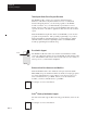
Chapter 10 Commands Power turn–on Start Is battery back-up enabled? No Erase RAM program Erase MTOP and port information in battery backed RAM Yes Has PROG1 or PROG2 been executed? Yes Copy EEPROM MTOP and port information to battery backed RAM No Is battery backed RAM MTOP and port information valid? No Store default MTOP and port information in battery backed RAM Yes Initialize ports using battery backed RAM Is RAM program present? Yes Execute RAM program No Is user EEPROM checksum corre
Chapter 10 Commands RAM Use the RAM command to tell the BASIC module interpreter to select the current program out of RAM. Use a LIST command (page 10 -9) to display and a RUN command (page 10 -19) execute the current program. Tip The execution time for a program running in RAM is the same as a program running from ROM. There is no performance improvement on a BASIC program by moving it to RAM. Important: RAM space is limited to 24K bytes.
Chapter 10 Commands REN Use the REN command to renumber program lines. Important: Chapter REN command updates the destination of GOSUB, GOTO, ONERR, ONTIME and ON GOTO statements (Chapter 11). If the target line number does not exist, or if there is insufficient memory to complete the task, no lines are changed and the message RENUMBER ERROR appears on the console screen.
Chapter 10 Commands ROM Use the ROM command to tell the BASIC module interpreter to select the current program out of EEPROM or EPROM. Use a LIST command (page 10 -9) to display and a RUN command (page 10 -19) to execute the current program. Tip The execution time for a program running in ROM is the same as a program running from RAM. There is no performance improvement on a BASIC program by moving it to RAM.
Chapter 10 Commands RROM Use the RROM command to tell the BASIC module interpreter to select the current program out of EEPROM or EPROM and then execute the program. This command is equivalent to typing ROM (page 10 -17) and then RUN (page 10 -19). Tip The execution time for a program running in ROM is the same as a program running from RAM. There is no performance improvement on a BASIC program by moving it to RAM.
Chapter 10 Commands RUN Use the RUN command to set all variables equal to zero, clear all BASIC evoked interrupts, and begin program execution with the first line number of the selected program. The RUN, CONT (page 10 -3), and RROM (page 10 -18) commands and the GOTO statement (page 11 -14) are the only ways you can place the BASIC module interpreter into Run mode from Command mode. Terminate program execution at any time by pressing Ctrl + C (page 10 -4) on the console device.
Chapter 10 Commands SNGLSTP Use the SNGLSTP command to initiate single-step program execution. If the number you specify with this command is zero, single-step execution is disabled. If the number is not zero, a break point is set before each line in the program. Start the program with the RUN command (page 10 -19). After each stop, type CONT (page 10 -3) to execute the next line. You can inspect variables or assign variables at each break point. SNGLSTP works only on programs executing from RAM.
Chapter 10 Commands VER Use the VER command to print the BASIC module sign-on message that displays the current version of the firmware. Syntax VER Return Example READY >VER PLC BASIC Module-Catalog Number 1771-DB/B Firmware Revision: A Allen-Bradley Company, Copyright 1989, 1990, 1991, 1992, 1993 1994 All rights reserved XFER Use the XFER command to transfer the current selected program in ROM to RAM and select RAM mode.
Chapter 10 Commands Command Line Calls What’s Next? These calls can only be executed from the command line. Use these calls to cause a function to occur within the BASIC module.
Chapter 11 Statements What’s in This Chapter? Chapter BASIC statements are programming instructions that control program flow or manipulate I/O or memory. Every statement begins with a line number, followed by a statement body, and terminated with a carriage return (CR) or a colon (:) in case of multiple statements per line number. You execute statements automatically within a BASIC program during Run mode.
Chapter 11 Statements CLEAR Use the CLEAR statement to set all variables equal to 0 and reset all BASIC evoked interrupts and stacks. This means that after you execute the CLEAR statement, you must execute an ONTIME statement (page 11 -25) before the module acknowledges the internal timer interrupts. ERROR trapping with the ONERR statement (page 11 -23) does not re-occur until you execute an ONERR ln num statement.
Chapter 11 Statements CLEARI Use the CLEARI statement to clear all of the BASIC evoked interrupts. The ONTIME (page 11 -25) interrupt is disabled after you execute the CLEARI statement. The CLEARI statement does not affect the free running clock that is enabled by the CLOCK1 statement (page 11 -5). CLOCK0 (page 11 -4) is the only module statement that can disable the free running clock. You can use this statement to selectively disable ONTIME interrupts during specific sections of your BASIC program.
Chapter 11 Statements CLOCK0 Use the CLOCK0 (zero) statement to disable or turn off the free running clock resident on the BASIC module. After you execute CLOCK0, the special function operator TIME (page 9 -19) no longer increments. CLOCK0 is the only module statement that can disable the free running clock. CLEAR (page 11 -2) and CLEARI (page 11 -3) do not disable the free running clock, only its associated ONTIME interrupt (page 11 -25).
Chapter 11 Statements CLOCK1 Use the CLOCK1 statement to enable the free running clock resident on the BASIC module. The special function operator TIME (page 9 -19) increments once every 5 milliseconds after you execute CLOCK1. CLOCK1 uses an internal timer to generate an interrupt once every 5 milliseconds. Because of this, the special function operator TIME has a resolution of 5 milliseconds. The special function operator TIME counts from 0 to 65535.995 seconds. After reaching a count of 65535.
Chapter 11 Statements DATA Use the DATA statement to specify the expressions that you can retrieve with a READ statement (page 11 -31). If you use multiple expressions per line, you must separate them with a comma. Every time a READ statement is encountered the next consecutive expression in the DATA statement is evaluated and assigned to the variable in the READ statement. You can place DATA statements anywhere within a program. They are not executed and do not cause an error.
Chapter 11 Statements DIM Use the DIM statement to reserve storage for arrays. The storage area is first assumed to be zero. Arrays in the BASIC module may have only one dimension and the size of the dimensioned array may not exceed 254 elements. Once you dimension a variable in a program you may not re-dimension it. An attempt to re-dimension an array causes an array size error and the module enters the Command mode.
Chapter 11 Statements DO-UNTIL Use the DO-UNTIL statement to set up loop control within a module program. All statements between the DO and the UNTIL rel expr are executed until the relational expression following the UNTIL statement is true. You can nest DO-UNTIL loops. The control stack (C-stack) stores all information associated with loop control. The C-stack is 157 bytes long. DO-UNTIL loops use 3 bytes of the C-stack. Do not improperly exit this loop or a C-stack error occurs.
Chapter 11 Statements DO-WHILE Use the DO-WHILE statement to set up loop control within a module program. This statement is similar to the DO-UNTIL rel expr (page 11 -8). All statements between the DO and the WHILE rel expr are executed as long as the relational expression following the WHILE statement is true. You can nest DO-WHILE statements. The control stack (C-stack) stores all information associated with loop control. The C-stack is 157 bytes long. DO-WHILE loops use 3 bytes of the C-stack.
Chapter 11 Statements END Use the END statement to terminate program execution. CONT (page 10 -3) does not operate if you use the END statement to terminate execution. An ERROR : CAN’T CONTINUE prints to the console. Always include an END statement to properly terminate a program.
Chapter 11 Statements FOR-TO-(STEP)-NEXT Use the FOR-TO-(STEP)-NEXT statement to set up and control program loops. If the STEP statement and the value are omitted, the increment value defaults to 1, therefore; STEP is an optional statement. The NEXT statement returns the loop to the beginning of the loop and adds the value of the STEP expr to the current index value. The current index value is then compared to the limit value of the index.
Chapter 11 Statements GET Use the GET statement in the Run mode. GET returns a result of zero in the Command mode. The GET operator reads the console input device. If a character is available from the console device, the value of the character is assigned to GET. After GET is read in the program, it is assigned the value of zero until another character is sent from the console device. The GET statement is read only once before it is assigned a value of zero.
Chapter 11 Statements GOSUB Use the GOSUB statement to cause the BASIC module to transfer control of the program to the line number the GOSUB statement references. In addition, the GOSUB statement saves the location of the next statement after the GOSUB on the C-stack, so that you can perform a RETURN statement (page 11 -34) to return control to that statement after the GOSUB executes. You may nest the GOSUB statement. The control stack (C-stack) stores all information associated with loop control.
Chapter 11 Statements GOTO Use the GOTO statement to cause BASIC to transfer control to the line number you specify. If line number you specify does not exist, the message ERROR: INVALID LINE NUMBER is printed to the console device and the BASIC module enters the Command mode. Unlike the RUN command (page 10 -19), if you execute the GOTO statement in the Command mode it does not clear the variable storage space or interrupts.
Chapter 11 Statements IF-THEN-ELSE Use the IF-THEN-ELSE statement to set up a conditional test. If you want to transfer control to different line numbers using the IF statement, you may omit the GOTO statement.
Chapter 11 Statements INPL Use the INPL statement to read an entire line (up to 254 characters) from the program port buffer. The line must be stored in a string variable. The INPL statement reads all characters from the program port until a carriage return or the 254 character limit is reached, whichever comes first. INPL does not echo characters read from the program port. Use the INPL# statement to read an entire line of characters from the PRT2 port buffer.
Chapter 11 Statements INPUT Use the INPUT statement to enter data from the console device during program execution. You may assign data to one or more variables with a single input statement. You must separate the variables with commas. You are prompted to enter data for each variable after the INPUT. If you do not enter enough data, the module prints TRY AGAIN on the console device. >10 INPUT A,C You can write the INPUT statement so that a descriptive prompt tells you what to enter.
Chapter 11 Statements LD@ Use the LD@ statement to retrieve floating point numbers stored with a ST@ statement (page 11 -35). The expression following the LD@ statement specifies the address where you want to store the number after executing the LD@. The LD@ statement places the number on the argument stack at the address location you specify with expr. You can use this statement with CALL 77 (page 13 -6) to retrieve variables from a protected area of memory.
Chapter 11 Statements LET Use the LET statement to assign a variable to the value of an expression. The = sign used in the LET statement is not an equality operator. It is a replacement operator. The statement should be read var is replaced expr. The word LET is always optional (ex. LET A = 2 is the same as A = 2). When LET is omitted the LET statement is called an IMPLIED LET. We use the word LET to refer to both the LET statement and the IMPLIED LET statement.
Chapter 11 Statements MODE Use the MODE command to set the port parameters of ports PRT1, PRT2, and DH-485. Important: If a argument (other than port name and communication rate) is blank, the argument defaults to the previously specified value for the argument.
Chapter 11 Statements NEXT Use the NEXT statement to return the FOR-TO-(STEP)-NEXT loop (page 11 -11) to the beginning of the loop and add the value of the index increment to the index. The current index value is then compared to the index limit to determine if another loop should be performed.
Chapter 11 Statements ONDF1 Use the ONDF1 statement to enable or disable the DF1 packet interrupt capability. (ONDF1 is equivalent to CALL 16, page 12 -10). You process the packet in an interrupt routine. Input the line number you want the program to jump to when a PRT2 receives a valid DF1 packet after the ONDF1 statement. Once you enable the DF1 packet interrupt, the BASIC module processor checks the port PRT2 receive buffer for a DF1 packet at the end of each line of BASIC.
Chapter 11 Statements ONERR Use the ONERR statement to handle arithmetic errors, if they occur, during program execution. The ONERR statement only traps arithmetic overflow (value too large), arithmetic underflow (value too small), divide by zero, and bad argument errors. All other errors are not trapped and cause the BASIC module to enter the Command mode.
Chapter 11 Statements ON-GOSUB Use the ON-GOSUB statement to transfer control to the line(s) you specified with the GOSUB statement (page 11 -13) when the value of the expression following the ON statement is encountered in the BASIC program. All comments that apply to GOSUB apply to the ON statement. If the expr after the ON is less than zero an ERROR: BAD ARGUMENT message is generated.
Chapter 11 Statements ONTIME Use the ONTIME expr, ln num statement to compensate for the incompatibility between the timer/counters on the microprocessor and the BASIC module. Your BASIC module can process a line in milliseconds while the timer/counters on the microprocessor operate in microseconds. The ONTIME statement generates an interrupt every time the special function operator, TIME (page 9 -19), is equal to or greater than the expression following the ONTIME statement.
Chapter 11 Statements ON-GOTO Use the ON-GOTO statement to transfer control to the line(s) you specified with the GOTO statement (page 11 -14) when the value of the expression following the ON statement is encountered in the BASIC program. All comments that apply to GOTO apply to the ON statement. If the expr after the ON is less than zero, an ERROR: BAD ARGUMENT message is generated and the BASIC module enters Command mode.
Chapter 11 Statements PH0. and PH1. Use the PH0. and PH1. statements to direct the BASIC module to print a number in hexadecimal format to the console device. These statements function in the same way as the PRINT statement (page 11 -29) except that the values printed are in a hexadecimal format. The PH0. statement suppresses two leading zeros if the number is less than 255 (0FFH). The PH1. statement prints out four hexadecimal digits. The character H always prints after the number when you use PH0.
Chapter 11 Statements POP Use the POP statement to remove values from the BASIC module argument stack. The value at the top of the argument stack is assigned to the variable following the POP statement and the argument stack is popped (decrements by 6 bytes). You can place values in the stack using the PUSH statement (page 11 -30). Important: If a POP statement executes and no number is in the argument stack, an A-stack error occurs and the BASIC module enters Command mode.
Chapter 11 Statements PRINT Use the PRINT statement to direct the BASIC module to output a value to the console device. You may print the value of expressions, strings, literal values, variables or text strings. You may combine the various forms in the print list by separating them with commas. If the list is terminated with a comma, the carriage return/line feed is suppressed. P. is a shorthand notation for PRINT. Values are printed next to one another with two intervening blanks.
Chapter 11 Statements PUSH Use the PUSH statement to place the arithmetic expression or expressions in the BASIC module argument stack. This statement evaluates the arithmetic expression, or expressions, following the PUSH statement and then places them in sequence on the argument stack. Each variable PUSHed increments the A-stack by 6 bytes. Chapter The PUSH and POP statements provide a simple means of passing parameters to call routines (see Chapters 12 and 13).
Chapter 11 Statements READ Use the READ statement to retrieve the expressions that you specified in the DATA statement (page 11 -6) and assign the value of the expression to the variable in the READ statement. The READ statement is always followed by one or more variables. If more than one variable follows a READ statement, separate them by a comma.
Chapter 11 Statements REM Use the REM command to specify a comment line in a BASIC program. Adding comment lines to a program makes the program easier to understand. Program lines that start with a REM command cannot be terminated with a colon (:). REM commands can be placed after a colon (:) in a program line. This allows you to place a comment on each line. Important: REM commands add time to program execution.
Chapter 11 Statements RETI Use the RETI statement to exit from an interrupt (ONDF1 (page 11 -22), ONTIME (page 11 -25), CALL 16 (page 12 -10,) or CALL 32 (page 12 -12) that is processed in a BASIC module program. The RETI statement functions the same as the RETURN statement (page 11 -34) except that it also clears a software interrupt flag so interrupts can again be acknowledged. If you do not execute the RETI statement in the interrupt procedure, all future interrupts are ignored.
Chapter 11 Statements RETURN Use the RETURN statement to return control to the statement following the most recently executed GOSUB (page 11 -13). Use one return for each GOSUB to avoid overflowing the control stack. This means that a subroutine you call with the GOSUB statement can call another subroutine with another GOSUB statement.
Chapter 11 Statements ST@ Use the ST@ statement to store BASIC module floating point numbers to a specified address. The expression following the ST@ statement specifies the address where you want the number stored in RAM. The ST@ statement takes the value on the top of the argument stack and stores it in RAM at the address location you specify by expr. You can use this statement with CALL 77 (page 13 -6) to store variables to a protected area of memory.
Chapter 11 Statements STOP Use the STOP statement to break program execution at specific points in a program. After a program is stopped you can display or modify variables. You can resume program execution with a CONT command (page 10 -3). The STOP statement allows for easy program debugging. Note that the line number printed out after execution of the STOP statement is the line number following the STOP statement, not the line number that contains the STOP statement.
Chapter 11 Statements STRING Use the STRING statement to allocate memory for strings. Initially, memory is not allocated for strings. If you attempt to define a string with a statement such as LET $(1)=“HELLO” before memory is allocated for strings, an ERROR: MEMORY ALLOCATION message is generated. The first expression in the STRING statement is the total number of bytes you want to allocate for string storage. The second expression gives the maximum number of bytes in each string.
Chapter 11 Statements Tip Important: Define strings in your program first, unless you are executing a CALL 77 (page 13 -6). Then, execute the CALL 77 first and define your strings immediately after. The BASIC module executes the equivalent of a CLEAR every time you execute the STRING statement. This is necessary because string variables and numeric variables occupy the same external memory space. After the STRING statement executes, all variables and arrays are wiped out.
Chapter 12 Call Routines 0 – 68 What’s in This Chapter? Chapter Calls 0 – 68 are described here. Calls 69 – 127 are described in Chapter 13. Chapter 7 gives you an overview of how to use these calls within your BASIC program. Use these calls within your BASIC program or from the command line. Important: CALL numbers above 127 are not valid and cause the BASIC module error–ERROR CALL ARGUMENT OUT OF RANGE.
Chapter 12 Call Routines 0–68 CALL 0: Reset Module This routine initiates a full reset. This is similar to a re-boot or pressing the reset button. The BASIC module reacts to this reset the same as it does when you turn on power to your I/O chassis backplane (page1 -13). Input and Output Arguments This routine has no input or output arguments. Syntax CALL 0 Example > 10 CALL 0 CALL 1: No Operation This routine does nothing. You return back to the main program.
Chapter 12 Call Routines 0–68 CALL 3: Timed BlockTransfer-Write Buffer Use this routine to receive data from the PLC processor. CALL 3 transfers the block-transfer-write (BTW) buffer to the auxiliary processor on the BASIC module for use in the next BTW request from the PLC processor. If a data transfer does not occur within 2 seconds the routine returns to your BASIC program with no new data. BASIC execution halts until the BTW occurs or the call times out.
Chapter 12 Call Routines 0–68 CALL 4: Set BlockTransfer-Write Length Use this routine to set the number of words (1-64) to transfer from the PLC processor to the BASIC module. The ladder logic program block-transfer length must match the set value. Important: Only use CALL 4 in your program once to set the block-transfer-write block length. Input and Output Arguments This routine has one input argument and no output arguments. The input argument is the number of words to BTW.
Chapter 12 Call Routines 0–68 CALL 6: Block-TransferWrite Buffer Use this routine to receive data from the PLC processor. CALL 6 transfers the block-transfer-write (BTW) buffer to the auxiliary processor on the BASIC module for use in the next BTW request from the PLC processor. This routine halts BASIC execution until a block-transfer write occurs. Whenever this call is active bit 1 (the sync BTW bit) of the PLC input image table is set. You can use this bit to trigger a BTR rung.
Chapter 12 Call Routines 0–68 CALL 8: Disable Interrupts (No Operation) This routine was used during EPROM programming in the 1771-DB, Series A BASIC module. If you initiate this call with a 1771-DB, Series B BASIC module, nothing happens. The call simply returns to the main program. CALL 9: Enable Interrupts (No Operation) This routine was used during EPROM programming in the 1771-DB, Series A BASIC module. If you initiate this call with a 1771-DB, Series B BASIC module, nothing happens.
Chapter 12 Call Routines 0–68 CALL 11: 16-Bit Binary to BASIC Floating Point Use this routine to convert 16-bit binary from PLC processor to BASIC floating point. See also CALL 21. Chapter See Chapter 8 for more information. Input and Output Arguments This routine has one input and one output argument. The input argument is the number (1 to 64) of the word in the write-data-transfer buffer you want to convert from 16-bit binary to BASIC format.
Chapter 12 Call Routines 0–68 CALL 13: 6-Digit Signed, Fixed Decimal BCD to BASIC Floating Point Use this routine to convert 6-digit BCD from the PLC processor to BASIC floating point. See also CALL 23. Chapter See Chapter 8 for more information. Input and Output Arguments This routine has one input and one output argument.
Chapter 12 Call Routines 0–68 CALL 15: SLC 16-Bit Unsigned Integer to BASIC Floating Point Chapter Use CALL 15 to convert an SLC 16-bit unsigned integer (or 16-bit binary) number from an SLC processor to a BASIC module floating-point number. This call is used to convert SLC unsigned integer numbers to BASIC floating point. Use it with DH-485 related calls. See also CALL 25. See Chapter 8 for more information. Input and Output Arguments This routine has one input and one output argument.
Chapter 12 Call Routines 0–68 CALL 16: Enable/Disable DF1 Packet Interrupt Use this routine to enable or disable the DF1 packet interrupt capability. This call has the same functionality as the ONDF1 statement (page 11 -22). You process the DF1 packet within an interrupt routine. To return to the point in the program before the interrupt occurred, execute a RETI (page 11 -33) within the routine.
Chapter 12 Call Routines 0–68 CALL 17: 4-Digit BCD to BASIC Floating Point Use this routine to convert 4-digit BCD from the PLC processor to BASIC floating point. See also CALL 27. Chapter See Chapter 8 for more information. Input and Output Arguments This routine has one input and one output argument. The input argument is the number (1-64) of the word in the block-transfer-write buffer you want to convert from 4-digit BCD to BASIC floating point format. The maximum value allowed is 0-9999.
Chapter 12 Call Routines 0–68 CALL 19: Disable the Control C Break Function Use CALL 19 to disable the Ctrl + C break function for LIST (page 10 -9) and RUN (page 10 -19) operations. Execute CALL 19 in a BASIC program or from Command mode. Cycling power returns the Ctrl + C function to normal operation if you disable it from the Command mode. Important: Ctrl + C is enabled by default. Input and Output Arguments This routine has no input or output arguments.
Chapter 12 Call Routines 0–68 CALL 21: BASIC Floating Point to 16-Bit Binary Use this routine to convert BASIC floating point to 16-bit binary PLC number. This routine takes a value between 0 and 65535 and converts it to its binary representative and stores it in the block-transfer-read buffer in one word. See also CALL 11. Chapter See Chapter 8 for more information. Input and Output Arguments This routine has two input and no output arguments.
Chapter 12 Call Routines 0–68 CALL 23: BASIC Floating Point to 6-Digit, Signed, Fixed Decimal BCD This routine converts a value from BASIC floating point format to 6-digit, signed, PLC BCD number in a 2 word format and places the converted value in the block-transfer-read buffer. See also CALL 13. Chapter See Chapter 8 for more information. Input and Output Arguments This routine has two input arguments and no output arguments. The first input value is the data or variable.
Chapter 12 Call Routines 0–68 CALL 24: BASIC Floating Point to SLC 16-Bit Signed Integer Chapter Use CALL 24 to convert a BASIC floating-point number to an SLC 16-bit signed integer SLC number and place result in the BASIC module output buffer, DH-485 common interface file. This call is used with DH-485 calls for BASIC module to SLC data conversion. See also CALL 14. See Chapter 8 for more information. The fractional part of the BASIC floating-point value is truncated.
Chapter 12 Call Routines 0–68 CALL 25: BASIC Floating-Point to SLC 16-Bit Binary Chapter Use CALL 25 to convert a BASIC module floating-point value between 0 and 65535 to its 16-bit binary (or unsigned integer) SLC number and store the result in the BASIC module output buffer DH-485 common interface file. This call is used with DH-485 calls for BASIC module to SLC data conversion. See also CALL 15. See Chapter 8 for more information.
Chapter 12 Call Routines 0–68 CALL 26: BASIC Floating Point to 3.3-Digit Signed BCD Use this routine to convert a variable in BASIC floating point format to a signed, 6-digit, fixed decimal point PLC number and store it in 2 words in the block-transfer-read buffer. See also CALL 39. Chapter See Chapter 8 for more information. Input and Output Arguments This routine has two input arguments and no output arguments. The first input value is the data (+999.999) or variable you want to convert to 3.
Chapter 12 Call Routines 0–68 CALL 28 Undefined. If you execute an undefined call, you receive the error message, “ERROR–UNSUPPORTED CALL.” CALL 29: Read/Write to a PLC/SLC Processor from the BASIC Module Internal String Use CALL 29 in conjunction with CALL 122 (page 13 -58) or CALL 123 (page 13 -66) to communicate between remote PLC processors and the BASIC module internal string without local PLC processor interaction.
Chapter 12 Call Routines 0–68 Syntax PUSH 49, 50, 122, or 123 for CALL 29 POP status of transaction the CALL you want to activate Example CALL 122 must be enabled with internal string only prior to executing CALL 29 in this example. Upon execution of CALL 29, an attempt is made to transfer one element from integer file 10, starting at element 0 of the PLC-5 processor at node 3, to the internal string $(1) of the BASIC module.
Chapter 12 Call Routines 0–68 CALL 30: PRT2 Port Support Parameter Set Use this routine to set up the parameters for the PRT2 port. The parameters you set are the number of bits/word, parity enable or disable/even or odd, number of stop bits, and handshaking (software, hardware, or none). The default communication rate is 1200 bit/s (jumper selected) and the default start bit is 1 (fixed). You can also use the MODE statement (page 11 -20) to set PRT2 port parameters.
Chapter 12 Call Routines 0–68 Syntax PUSH number of bits/word PUSH parity PUSH number of stop bits PUSH software handshaking PUSH hardware handshaking CALL 30 Example >100 >120 >140 >160 >180 >190 PUSH PUSH PUSH PUSH PUSH CALL 8 :REM 8 BITS/WORD 0 :REM NO PARITY 1 :REM 1 STOP BIT 0 :REM NO SOFTWARE HANDSHAKING 0 :REM IGNORE CTS, DCD and DSR 30 :REM SET UP PRT2 PORT –or– >100 PUSH 8, 0, 1, 0, 0:CALL 30 CALL 31: Display PRT2 Port Parameters This routine displays the current PRT2 port configuration on t
Chapter 12 Call Routines 0–68 CALL 32: Enable/Disable Processor Interrupt Important: This call requires the BASIC module jumper JW5 to be in 16 point mode (page 1 -7). Use CALL 32 to allow the PLC processor to interrupt the BASIC module. When enabled the BASIC module monitors PLC output bit 16 for a 0 to 1 transition at the end of every BASIC line and generates the interrupt if the bit is set. The PLC ladder logic should then clear the PLC output bit 16.
Chapter 12 Call Routines 0–68 CALL 33: Transfer Data from PRT1 or PRT2 to the BTR Buffer Tip Important: This call requires the BASIC module jumper JW5 to be in 16 point mode (page 1 -7). Use CALL 33 to transfer data from the BASIC module ASCII ports directly to the BTR buffer and/or an internal string within the BASIC module. This call is useful for reading bar code data and sending it to the PLC processor or an internal string.
Chapter 12 Call Routines 0–68 1. When data is available from the port, the BASIC module automatically transfers the data into the BTR buffer. The module also checks the same port for data at the end of each line of BASIC code. Reserved PLC Backplane BYTE COUNT PRT1 DATA PRT2 PLC Processor RS–232, RS–422, or RS–485 Network AVAILABLE DATA BTR Buffer BASIC Module 2. External Device The BASIC module places the byte count of the valid data into the lower byte of BTR word 1 of the BTR buffer.
Chapter 12 Call Routines 0–68 4. The ladder logic program of the PLC processor retrieves the data from the input image table and performs a block transfer Block Transfer PRT2 PLC Backplane PRT1 PLC Processor 5. BASIC Module The BASIC module resets the bit in the PLC input image table on the same end of the scan cycle in which the block transfer is performed.
Chapter 12 Call Routines 0–68 Input Argument One The first input argument is the source port number (PRT1 or PRT2) of the BASIC module. A zero disables all previously active CALL 33 commands. 0 = disable CALL 33 for all active ports enabled by earlier CALL 33s 1 = PRT1 is source 2 = PRT2 is source Input Argument Two The second input argument is the maximum number of 8-bit characters you want to copy from the BASIC serial port to the destination file.
Chapter 12 Call Routines 0–68 Input Argument Five The fifth input argument should always be 1. Input Argument Six The sixth input argument is the string number. If the fourth input argument does not select internal string usage, the value of this input argument is ignored, but you must still PUSH the argument. Input Argument Seven The seventh input argument is the byte swap selection: 0 = data bytes transferred from the BASIC port are not swapped when passed to the destination.
Chapter 12 Call Routines 0–68 Syntax PUSH source port number PUSH maximum number of characters to be PUSH decimal value of character delimiter PUSH selection of BTR buffer and/or string PUSH 1 PUSH string number PUSH byte swap selection CALL 33 POP CALL 33 status transferred Example >1 >05 REM EXAMPLE PROGRAM PUSH 64 : CALL 5 : REM SET BLOCK TRANSFER READ LENGTH >10 REM ENABLE CALL 33 INTERRUPTS >20 PUSH 1 : REM PRT1 ACTIVE FOR CALL 33 >30 PUSH 10 : REM RECEIVING 10 BYTES OF DATA MAXIMUM >40 PUSH 13 : R
Chapter 12 Call Routines 0–68 CALL 34: Transfer Data from the BTW buffer to PRT1 or PRT2 Important: This call requires the BASIC module jumper JW5 to be in 16 point mode (page 1 -7). Tip This call is useful for writing to a remote display device (operator interface) directly from the PLC processor or an internal string. Once you set up and enable this operation it is performed transparently in the background while the BASIC module executes a BASIC program in the foreground.
Chapter 12 Call Routines 0–68 2. The ladder logic program of the PLC processor must latch the output image table, bit 11 or bit 13 to inform the BASIC module that valid data is available. Bit 11 indicates that data is available for PRT1 and bit 13 indicates that data is available for PRT2. Latch Output Image Table Bit 11 or 13 PRT1 PLC Backplane PRT2 PLC Processor 3.
Chapter 12 Call Routines 0–68 6. The BASIC module resets the input image table bit 11 or bit 13 on the same end of scan cycle in which the output image table bit 11 or bit 13 was reset. Reset Input Image Table Bit 11 or 13 PLC Processor PLC Backplane BASIC Module Transfers continue in this manner until you re-execute the call for the port with different input parameters. If this occurs, the previous CALL 34 for the port is automatically disabled and the new CALL 34 takes effect.
Chapter 12 Call Routines 0–68 Input Argument Two The second input argument is always 0. Input Argument Three The third input argument is always 1. Input Argument Four The fourth input argument is the internal string number. If the second input argument does not select internal string usage, the value of this input argument is ignored (but you must still PUSH it). If the data exceeds the string length, the remaining data is truncated.
Chapter 12 Call Routines 0–68 Syntax PUSH destination port number PUSH 0 PUSH 1 PUSH string number PUSH byte swap selection CALL 34 POP CALL 34 status and/or internal string Example >01 PUSH 64 : CALL 4 : REM SET BLOCK TRANSFER WRITE LENGTH >10 REM ENABLE CALL 34 INTERRUPTS >20 PUSH 2 : REM SEND DATA TO PRT1 >30 PUSH 0 : REM ALWAYS 0 >40 PUSH 1 : REM ALWAYS 1 >50 PUSH 0 : REM STRING NUMBER/NOT USED HERE >60 PUSH 1 : REM ENABLE BYTE SWAPPING >70 CALL 34 >80 POP S : REM STATUS OF CALL SETUP >90 IF (S<>0) T
Chapter 12 Call Routines 0–68 CALL 35: Retrieve Numeric Input Character from PRT2 Port Use this routine to retrieve the current character in the 255 character, PRT2 port receive buffer and convert it to its decimal representation. The PRT2 port receives data your device transmits and stores it in this buffer. You can use the GET# statement (page 11 -12) in place of CALL 35. Input and Output Arguments This routine has no input arguments and one output argument.
Chapter 12 Call Routines 0–68 CALL 36: Get the Number of Characters in the PRT2 Port Buffer Use this routine to retrieve the number of characters in the buffer you choose. Input and Output Arguments This routine has one input and one output argument. The input argument is the buffer you want to examine: 0 = transmit buffer 1 = receive buffer The output argument is the number of characters in the specified buffer.
Chapter 12 Call Routines 0–68 CALL 38: Expanded ONERR Restart Use CALL 38 to expand the type of errors the ONERR statement (page 11 -23) traps and handles. The ONERR statement only allows the BASIC module to jump to an error handling routine when it encounters an arithmetic error (number too large, number too small, bad argument or division by zero occurs). All other errors cause the module to enter Command mode.
Chapter 12 Call Routines 0–68 Status code Description 17 18 19 no DATA available for READ DF1 cannot be enabled (JW4 in wrong position) • illegal use of PRT2 while DF1 is enabled • illegal use of PRT2 while background DF1 task is enabled • attempted to transmit DF1 packet before DF1 is enabled • attempted to transmit DF1 packet of incorrect length arithmetic overflow (value too large for range) bad line number JW5 in 8-point position arithmetic underflow (value too small for range) bad argument 20 21 2
Chapter 12 Call Routines 0–68 CALL 39 : 3.3-Digit Signed, BCD to BASIC Floating Point Chapter Use this routine to convert 3.3-digit BCD from the PLC processor to BASIC floating point. See also CALL 26. See Chapter 8 for more information. Input and Output Arguments This routine has one input and one output argument. The input argument is the number (1-64) of the first word (3.3-digit BCD is sent to the BASIC module in two processor words) of the write-block-transfer buffer you want to convert from 3.
Chapter 12 Call Routines 0–68 CALL 40: Set the Wall Clock Time (Hour, Minute, Second) Use this routine to set the wall clock time functions. Important: The Series B, BASIC module does not update the wall clock for Daylight Savings Time. You must do this manually. (The Series A, BASIC module, revisions A, B, C and D update the fall time change correctly but update the spring time change on the third weekend of April instead of the first weekend.
Chapter 12 Call Routines 0–68 CALL 41: Set Wall Clock Date (Day, Month, Year) Use this routine to set the wall clock date functions. Input and Output Arguments This routine has three input arguments and no output arguments. The input arguments are the wall clock date functions: D = day M = month Y = year Syntax PUSH date 1–31 PUSH month 1–12 PUSH year 0–99 CALL 41 Example Program the wall clock for the 16th day of June 1994.
Chapter 12 Call Routines 0–68 CALL 43: Retrieve Date/Time String Use CALL 43 to retrieve the current date and time as a string. Input and Output Arguments This routine has one input argument and no output arguments. The input argument is the number of the string to receive the date/time (dd/mm/yy and hh:mm:ss). You must use the STRING statement (see page 11 -37) to allocate a minimum of 18 characters for the string. This requires you to set the maximum length for all strings to at least 18 characters.
Chapter 12 Call Routines 0–68 CALL 45: Retrieve Time String Use CALL 45 to retrieve the current time in a string (hh:mm:ss). Input and Output Arguments This routine has one input argument and no output arguments. The input argument is the number of the string to receive the time. You must use the STRING statement (see page 11 -37) to allocate a minimum of 8 characters for the string.
Chapter 12 Call Routines 0–68 CALL 47: Retrieve Day of Week String Use CALL 47 to retrieve the current day of week as a three character string. Input and Output Arguments This routine has one input argument and no output arguments. The input argument is the number of the string to receive the day of week. You must use the STRING statement (see page 11 -37) to allocate a minimum of 3 characters/string. Strings returned are SUN, MON, TUE, WED, THU, FRI, SAT.
Chapter 12 Call Routines 0–68 CALL 49: Read Remote DH-485 SLC Data File Important: This call requires the BASIC module to be in 16 point mode (page 1 -7). Use CALL 49 to read up to 63 words of data from a remote DH-485 node and place in the BTR buffer or a string within the BASIC module. Tip This call is useful for reading bar code data and sending it to the PLC processor or an internal string.
Chapter 12 Call Routines 0–68 3. When data is available, the BASIC module transfers the data into BTR buffer. The DH-485 status word is placed in lower byte of word 1. The upper byte of BTR word 1 is reserved. Reserved Status 1 DATA 2–64 BTR Buffer 4. BASIC Module The BASIC module sets the input image table, bit 14 and performs a block transfer read. Set Input Image Table Bit 14 PLC Backplane PLC Processor 5.
Chapter 12 Call Routines 0–68 This call is active until you re-execute it with different input parameters. Input and Output Arguments This call has ten input arguments and one output argument.
Chapter 12 Call Routines 0–68 Input Argument Four The fourth input argument is the file type to be read from the remote device. This number is ignored if the CIF is chosen in the first parameter (assumes integer file). If the file type is not one of these listed below, the status equals 2 and the read message does not take place. Enter the file type code as shown below when you PUSH the fourth input parameter.
Chapter 12 Call Routines 0–68 Input Argument Eight The eighth input argument is the selection of the BTR buffer and/or string: 0 = BTR buffer 2 = internal string 4 = BTR buffer and internal string If you choose internal string (2), you can execute CALL 29 (page 12 -18) to initiate each data transfer without requiring PLC processor interaction. Input Argument Nine The ninth input argument is always 1. Input Argument Ten The tenth input argument is the string number.
Chapter 12 Call Routines 0–68 Example >10 >15 >16 >20 >30 >40 >50 >60 >70 >80 >90 >100 >110 >120 >130 >140 REM ENABLE REMOTE DH-485 READ COMMAND INTERRUPT PUSH 64: CALL 4: REM SET BLOCK TRANSFER WRITE LENGTH PUSH 64: CALL 5: REM SET BLOCK TRANSFER READ LENGTH PUSH 2 : REM SLC TYPED READ COMMAND PUSH 2 : REM NODE ADDRESS OF REMOTE SLC PUSH 7 : REM FILE NUMBER OF REMOTE SLC PUSH ASC(N) : REM FILE TYPE OF REMOTE SLC PUSH 100 :REM REMOTE ELEMENT OFFSET INTO REMOTE SLC FILE PUSH 20 : REM NUMBER OF ELEMENTS TO
Chapter 12 Call Routines 0–68 CALL 50: Write to Remote DH-485 SLC Data Important: This call requires the BASIC module jumper JW5 to be in 16 point mode (page 1 -7). Use CALL 50 to write up to 63 words of data from the BTW buffer and/or a string within the BASIC module to the remote DH-485 file at the node address you designate. Tip This call is useful for writing to a display device directly from the PLC processor or an internal string.
Chapter 12 Call Routines 0–68 3. The BASIC module sets bit 15 in the input image table to inform the PLC processor that a block transfer write will be performed. Set Input Image Table Bit 15 PLC Backplane PLC Processor 4. BASIC Module The BASIC module performs a block transfer to receive the data. Reserved Reserved PLC Backplane DATA 2–64 PLC Processor BTW Buffer BASIC Module 5. The PLC processor unlatches bit 15 in the output image table.
Chapter 12 Call Routines 0–68 7. The BASIC module assembles the DH-485 packet and sends it to the remote device on the DH-485 network DH485 DH-485 Network DATA BUFFER Remote Device BASIC Module 8. The BASIC module places the DH-485 transfer status into the BTR buffer word 1. Reserved Status 1 PLC Backplane BTR Buffer PLC Processor 9.
Chapter 12 Call Routines 0–68 Once this call is active, it remains active and sends data to the remote node whenever the PLC processor handshaking is accomplished. Input and Output Arguments This call has ten input arguments and one output argument.
Chapter 12 Call Routines 0–68 Input Argument Four The fourth input argument is the file type you want to write to the remote device. This number is ignored if choose the CIF in the first parameter (assumes integer file). If the file type is not one of those listed, the status equals 2 and the write message does not take place.
Chapter 12 Call Routines 0–68 Input Argument Eight The eighth input argument is the selection of the source BTW buffer or the internal string: 0 = BTW buffer 2 = internal string If you choose internal string (2), you can execute CALL 29 (page 12 -18) to initiate each data transfer without requiring PLC processor interaction. The output table bit 15 also initiates a string transaction. Input Argument Nine The ninth input argument is always 1. Input Argument Ten The tenth input argument is the string number.
Chapter 12 Call Routines 0–68 Syntax PUSH type of DH-485 WRITE command PUSH remote DH-485 device node number PUSH remote DH-485 device file number PUSH remote DH-485 device file type PUSH element offset into destination file PUSH number of elements to be transferred PUSH message time-out value(X100MS) PUSH block transfer write buffer PUSH 1 PUSH Internal string number CALL 50 Example >10 >20 >30 >40 >50 >60 >70 >80 >90 >100 >110 >120 >130 >140 >150 >160 12 -56 PUSH 64 : CALL 4 : REM SET BLOCK TRANSFER W
Chapter 12 Call Routines 0–68 Sample Ladder Logic Rung 2:0 N10:0 O:001 (L) 15 0 Rung enable bit (N10:0 used as example) N10:0 (U) 0 Rung 2:1 I:001 15 O:001 BTW BLOCK TRANSFER WRITE Rack 00 Group 1 Module 0 Control Block N7:0 Data file N10:10 Length 64 Continuous N 15 (EN) (DN) (ER) O:001 (U) 15 Rung 2:2 I:001 16 N6:0 BTR BLOCK TRANSFER READ Rack 00 Group 1 Module 0 Control Block N6:0 Data file N11:10 Length 1 Continuous N 15 (EN) (DN) (ER) Rung 2:3 [END OF FILE] 12 -57
Chapter 12 Call Routines 0–68 CALL 51 Undefined. If you execute an undefined call, you receive the error message, “ERROR–UNSUPPORTED CALL.” CALL 52: Retrieve Date String Use CALL 52 to retrieve the current date in a string (dd/mm/yy). Input and Output Arguments This routine has one input argument and no output arguments. The input argument is the number of the string to receive the date. You must use the STRING statement (see page 11 -37) to allocate a minimum of 9 characters for the string.
Chapter 12 Call Routines 0–68 CALL 60: String Repeat Use this routine to repeat a character and place it in a string. You can use the string repeat when designing output formats. You cannot repeat more characters than the string’s maximum length. Input and Output Arguments This routine has two input arguments and no output arguments. The first input argument is the number of times you want to repeat the character.
Chapter 12 Call Routines 0–68 CALL 61: String Append (Concatenation) Use this routine to append one string to the end of another string. If the resulting string is longer than the maximum string length, the append characters are lost. This is a string concatenation assignment. (Ex. $(1)=$(1)+$(2)). Input and Output Arguments This routine has two input arguments and no output arguments. The first input argument is the string number of the string you want appended.
Chapter 12 Call Routines 0–68 CALL 62: Number to String Conversion Use this routine to convert a number or numeric variable into a string. You must use the STRING statement (see page 11 -37) to allocate a minimum of 14 characters for the string. If the exponent of the value you want to convert is 100 or greater, you must allocate 15 characters. Error checking traps string allocation of less than 14 characters only. Input and Output Arguments This routine has two input arguments and no output arguments.
Chapter 12 Call Routines 0–68 CALL 63: String to Number Conversion Use this routine to convert the first decimal number found in the string you specify to a number, and place this number on the argument stack. Valid numbers and associated characters are 0, 1, 2, 3, 4, 5, 6, 7, 8, 9, ., E, +, -. The comma is not a valid number character and terminates the conversion. Input and Output Arguments This routine has one input argument and two output arguments.
Chapter 12 Call Routines 0–68 CALL 64: Find a String in a String Use this routine to find a string within a string. It locates the first occurrence (position) of this string. This routine is similar to the ANSI BASIC INSTR$(findstr$,str$). (Example: L=INSTR$($(1),$(2)) Input and Output Arguments This routine has two input arguments and one output argument. The first input is the string you want to find. The second input is the string you want to search for a match.
Chapter 12 Call Routines 0–68 CALL 65: Replace a String in a String Use this routine to replace a string within a string. Input and Output Arguments This routine has three input arguments and no output arguments. The first input argument is the string number of the new string to replace the old string. The second input argument is the string number of the old string to be replaced by the new string. The third input argument is the base string’s string number.
Chapter 12 Call Routines 0–68 CALL 66: Insert String in a String Use this routine to insert a string within another string. Input and Output Arguments This routine has three input arguments and no output arguments. The first argument is the position at which to begin the insert. The second argument is the string number of the characters you want to insert into the base string. The third argument is the string number of the base string.
Chapter 12 Call Routines 0–68 CALL 67: Delete String from a String Use this routine to delete a string from within another string. Important: This routine deletes only the first occurrence of the string. Input and Output Arguments This routine has two input arguments and no output arguments. The first argument is the base string number. The second is the string number of the string you want to delete from the base string.
Chapter 12 Call Routines 0–68 CALL 68: Determine Length of a String Use this routine to determine the length of a string. To properly determine the length of a string you must terminate the string with a CR character. If you use the ASC string operator (page 9 -14) to fill the string, you must add a CR as the last character to terminate the string. Input and Output Arguments This routine has one input and one output argument. The input is the string number on which the routine acts.
Chapter 12 Call Routines 0–68 Notes: 12 -68
Chapter 13 Call Routines 69–127 What’s in This Chapter? Chapter There are 128 BASIC calls. Calls 69 – 127 are described here. Calls 0 – 68 are described in Chapter 12. Chapter 7 gives you an overview of how to use these calls within your BASIC program. Use these calls within your BASIC program or from the command line. Important: CALL numbers above 127 are not valid and cause the BASIC module error–ERROR CALL ARGUMENT OUT OF RANGE.
Chapter 13 Call Routines 69–127 CALL 69 Undefined. If you execute an undefined call, you receive the error message, “ERROR–UNSUPPORTED CALL.” CALL 70: ROM to RAM Program Transfer Use this routine to shift program execution from a running ROM program to the beginning of the RAM program. Important: The first line of the RAM program is not executed. We recommend that you make it a remark.
Chapter 13 Call Routines 69–127 CALL 71: ROM/RAM to ROM Program Transfer Use this routine to transfer from a running ROM or RAM program to the beginning of any available ROM program. Important: The first line of the ROM program is not executed. We recommend that you make it a remark. Important: There must be a next line in the ROM or RAM routine, otherwise unpredictable events could occur that may destroy the contents of RAM.
Chapter 13 Call Routines 69–127 CALL 72: RAM/ROM Return Use this routine to return to the routine that called this ROM/RAM routine. Execution begins on the line after the line that called the ROM/RAM routine. This routine works one layer deep. You may go back to the last called program’s next line. Important: There must be a next line in the ROM or RAM routine, otherwise unpredictable events could occur that may destroy the contents of RAM.
Chapter 13 Call Routines 69–127 CALL 73: Battery-Backed RAM Disable Use CALL 73 to disable the battery-backed RAM and purge reset. You see “Battery Backup Disabled” when you execute this call. The next power loss destroys the contents of RAM. When you reapply power (if JW7 is enable, page 1 -9), RAM is cleared and battery back-up is automatically re-enabled. Input and Output Arguments This routine has no input or output arguments.
Chapter 13 Call Routines 69–127 CALL 77: Protected Variable Storage Use CALL 77 to reserve the top of RAM memory for protected variable storage. Values are saved if you enabled CALL 74 (page13 -5). You store values with the ST@ (page11 -35) statement and retrieve them with the LD@ (page11 -18) statement. Each variable you store requires 6 bytes of storage space. You must subtract 6 times the number of protected variables you are storing from MTOP. This reduces the available RAM memory.
Chapter 13 Call Routines 69–127 >60 >70 >80 >90 >100 LD@ POP LD@ POP REM 14335:REM REMOVE K FROM PROTECTED AREA K 14329 L USE LD@ AFTER POWER LOSS AND BATTERY BACK-UP IS USED Using Protected Variable Storage Area >PRINT MTOP 14335 >PRINT MTOP-24 14311 >PUSH 14311 (NEW MTOP ADDRESS) >CALL 77 >90 M1=14335 : REM BEGIN STORING HERE >100 PUSH A, B, C, D Using the ST@ and LD@ Commands in a DO Loop >200 >210 >220 >230 >290 >300 >310 >320 >330 >360 >370 DO ST@ M1 M1=M1-6 :REM EACH VARIABLE = 6 BYTES UNTIL M1=
Chapter 13 Call Routines 69–127 CALL 78: Set Program Port Communication Rate Use CALL 78 to change the program port communication rate from its default value (1200 bit/s) to one of the following: 300, 600, 1200, 2400, 4800, 9600 or 19200 bit/s. The default communication rate for the program port is 1200 bit/s if port PRT1 is configured as the program port or 19200 bit/s if port DH485 is configured as the program port. PUSH the desired communication rate and CALL 78.
Chapter 13 Call Routines 69–127 CALL 80: Check Battery Condition Use CALL 80 to check the module’s battery condition. Chapter Refer to Chapter 3 for information on how to change the battery. Important: Refer to Guidelines for Handling Lithium Batteries (publication number AG-5.4 to properly dispose of the lithium battery. Input and Output Arguments This routine has no input arguments and one output argument.
Chapter 13 Call Routines 69–127 CALL 81: User PROM Check and Description Use CALL 81 before storing a program in the EEPROM memory.
Chapter 13 Call Routines 69–127 CALL 82: Check User Memory Module Map Use CALL 82 to check the user PROM and display a map of where all the BASIC programs are stored. Use this routine as an aid for assembly language programming. With this call you can determine where the empty space in the memory module is located and how much space is available. Input and Output Arguments This routine has no input or output arguments.
Chapter 13 Call Routines 69–127 CALL 84: Transfer DH-485 Common Interface File to BASIC Input Buffer Use CALL 84 to transfer up to 40 words starting at the designated offset of the DH-485 Common Interface File to the BASIC module input buffer starting at the same designated offset from word 0. This call does not interrupt nor is it interrupted by a DH-485 read or write from or to the DH-485 common interface file. Input and Output Arguments This routine has two input arguments and one output argument.
Chapter 13 Call Routines 69–127 CALL 85: Transfer BASIC Output Buffer to DH-485 Common Interface File Use CALL 85 to transfer up to 40 words starting at the designated offset of the BASIC output buffer to the DH-485 Common Interface File starting at the same designated offset from word 0. This call does not interrupt nor is it interrupted by a DH-485 read or write from or to the DH-485 common interface file. Word integrity is guaranteed during this transfer. File integrity is not.
Chapter 13 Call Routines 69–127 CALL 86: Check DH-485 Interface File Remote Write Status Use CALL 86 to determine if the DH-485 Common Interface File located in the BASIC module was updated since the last time you checked. Input and Output Arguments This routine has no input arguments and one output argument.
Chapter 13 Call Routines 69–127 CALL 87: Check DH-485 Interface File Remote Read Status Use CALL 87 to determine if the DH-485 Common Interface File located in the BASIC module was read by a device on the DH-485 Serial Communications Link since the last time you checked. Input and Output Arguments This routine has no input arguments and one output argument.
Chapter 13 Call Routines 69–127 CALL 88: BASIC Floating Point to PLC-5 Floating Point Use this call to convert BASIC floating point to PLC-5 floating point in a two-word format and place the converted value in the block transfer read buffer. See also CALL 89. Chapter See Chapter 8 for more information. The BASIC module floating point number is an 8-digit BCD floating point number. The range of the BASIC module floating point number is; ±1E–127 to ±.
Chapter 13 Call Routines 69–127 CALL 89: PLC-5 Floating Point to BASIC Floating Point Use this call to convert PLC-5 floating point to BASIC floating point. See also CALL 88. Chapter See Chapter 8 for more information. The PLC-5 floating point number is a 7-digit binary floating point number (IEEE Float 32- bit value). The range of the PLC-5 floating point number: ±1.1754944E–38 to ±3.4028237E+38 The BASIC module floating point number is an 8-digit BCD floating point number.
Chapter 13 Call Routines 69–127 CALL 90: Read Remote DH-485 Data File to BASIC Input Buffer Use CALL 90 to read up to 40 words from the designated node address, file number, file type, and element offset of a remote DH-485 data file to the BASIC module input buffer starting at word 100. Input and Output Arguments This routine has six input arguments and one output argument.
Chapter 13 Call Routines 69–127 Input Argument Four The fourth input argument is the starting element offset within the file on the remote device (0 to 32767). If the number is not within the range 0 to 32767, then the output argument equals 12, and the transfer does not take place. Important: The offset is twice of what is expected. For example, if an offset of 3 is PUSHed, the data is written to the remote DH-485 data file beginning at element 6.
Chapter 13 Call Routines 69–127 Output Argument One The output argument specifies the status of the message instruction.
Chapter 13 Call Routines 69–127 Syntax PUSH remote device node address PUSH remote device file number PUSH remote device file type PUSH starting element offset (x2) of remote PUSH number of elements to be transferred PUSH message time-out value CALL 90 POP status of message instruction device file Example >10 >20 >30 >40 >50 >60 >70 >80 >90 PUSH 1 : REM REMOTE NODE ADDRESS = 1 PUSH 5 : REM REMOTE FILE 5 PUSH ASC(C) : REM FILE TYPE = COUNTER PUSH 0 : REM OFFSET = 0 PUSH 10 : REM ELEMENT LENGTH = 10 = 30
Chapter 13 Call Routines 69–127 CALL 91: Write BASIC Output Buffer to Remote DH-485 Data File Use CALL 91 to write up to 40 words starting at word 100 of the BASIC module output buffer to the remote DH-485 data file at the designated node address, file number, file type, and element offset. Input and Output Arguments This routine has six input arguments and one output argument.
Chapter 13 Call Routines 69–127 Input Argument Four The fourth input argument is the starting element offset within the file on the remote device (0 to 255). If the number is not within the range (0 to 255), then the output argument equals 12, and transfer does not take place. Important: The offset is twice of what is expected. For example, if an offset of 3 is PUSHed, the data is written to the remote DH-485 data file beginning at element 6.
Chapter 13 Call Routines 69–127 Output Argument One The output argument specifies the status of the message instruction.
Chapter 13 Call Routines 69–127 Syntax PUSH remote device node address PUSH remote device file number PUSH remote device file type PUSH starting element offset (x2) of remote device PUSH number of elements to be transferred PUSH message time-out value CALL 91 POP status of message instruction file Example >1 >10 >20 >30 >40 >50 >60 >70 >80 >90 REM EXAMPLE PROGRAM PUSH 1 : REM REMOTE NODE ADDRESS = 1 PUSH 7 : REM REMOTE FILE 7 PUSH ASC(N) : REM FILE TYPE = INTEGER PUSH 0 : REM OFFSET = 0 PUSH 10: REM WOR
Chapter 13 Call Routines 69–127 CALL 92: Read Remote DH-485 Common Interface File to BASIC Input Buffer Use CALL 92 to read up to 40 words from the remote DH-485 Common Interface File of the designated node address, starting at the designated word offset to the BASIC module input buffer starting at word 100. Input and Output Arguments This routine has four input arguments and one output argument.
Chapter 13 Call Routines 69–127 Output Argument One The output argument specifies the status of the message instruction.
Chapter 13 Call Routines 69–127 Syntax PUSH remote device node address PUSH starting element offset (x2) of remote PUSH number of words to be transferred PUSH message time-out value CALL 92 POP status of message instruction device file Example >1 REM EXAMPLE PROGRAM >30 PUSH 1 : REM REMOTE NODE ADDRESS = 1 >40 PUSH 0 : REM OFFSET = 0 >50 PUSH 10 : REM WORD LENGTH = 10 >60 PUSH 5 REM TIME-OUT VALUE = 0.
Chapter 13 Call Routines 69–127 CALL 93: Write Output Buffer to Remote DH-485 Common Interface File Use CALL 93 to write up to 40 words starting at word 100 of the BASIC module output buffer to the remote DH-485 Common Interface File at the designated node address, starting at the designated word offset. Input and Output Arguments This routine has four input arguments and one output argument.
Chapter 13 Call Routines 69–127 Output Argument One The output argument specifies the status of the message instruction. Upon return from the call, the output argument has this definition.
Chapter 13 Call Routines 69–127 Syntax PUSH remote device node address PUSH starting element offset (x2) of remote PUSH number of words to be transferred PUSH message time-out value CALL 93 POP status of message instruction device file Example >1 >30 >40 >50 >60 >70 >80 >90 REM EXAMPLE PROGRAM PUSH 1 : REM REMOTE NODE ADDRESS = 1 PUSH 0 : REM OFFSET = 0 PUSH 10 : REM WORD LENGTH = 10 PUSH 5 : REM THE TIME-OUT VALUE = 0.
Chapter 13 Call Routines 69–127 CALL 94: Display Current PRT1 Port Setup Use CALL 94 to display the current PRT1 port configuration on the terminal screen. Input and Output Arguments This routine has no input or output arguments.
Chapter 13 Call Routines 69–127 CALL 96: Clear PRT1 Receive/Transmit Buffers Use CALL 96 to clear port PRT1 receive and transmit buffers. Input and Output Arguments This routine has one input and no output argument.
Chapter 13 Call Routines 69–127 CALL 98: Disable Port PRT2 DTR Signal Use CALL 98 to disable the Data Terminal Ready (DTR) signal from PRT2. CALL 97 re-enables the DTR signal. Input and Output Arguments This routine has no input and no output arguments. Syntax CALL 98 Example >1 REM EXAMPLE PROGRAM >10 CALL 98 : REM DISABLE DTR SIGNAL >30 END CALL 99: Reset Print Head Pointer Use CALL 99 to reset the internal print head character counter of your printer when printing out wide forms.
Chapter 13 Call Routines 69–127 CALL 100: Download and Program Assembly Language Code to EEPROM Use this call to store a file in user EEPROM through the program port of the BASIC module. The file must be in Intel Hex format. No checks are made on the addresses you are programming. An error message is generated to the program port if the EEPROM programming sequence fails. This call allows you to program assembly language programs in the BASIC module.
Chapter 13 Call Routines 69–127 CALL 103: Print PRT1 Transmit Buffer and Pointer Use CALL 103 to print the complete PRT1 transmit buffer with address, front pointer, and number of characters in the buffer to the console screen. Use this information as a troubleshooting aid. It does not affect the contents of the buffer. Input and Output Arguments This routine has no input or output arguments.
Chapter 13 Call Routines 69–127 CALL 104: Print PRT1 Receive Buffer and Pointer Use CALL 104 to print the complete PRT1 receive buffer with address, front pointer, and number of characters in the buffer to the console screen. Use this information as a troubleshooting aid. It does not affect the contents of the buffer. Input and Output Arguments This routine has no input or output arguments.
Chapter 13 Call Routines 69–127 CALL 106 – 107 Undefined. If you execute an undefined call, you receive the error message, “ERROR–UNSUPPORTED CALL.” CALL 108: Enable DF1 Driver Communications Use CALL 108 to enable DF1 driver communications via port PRT2. You can only enable this device if the operating mode jumper JW4 (page 1 -6) is in the correct position. See CALL 113 (page13 -47 ) to disable the DF1 driver. Input and Output Arguments This routine has six input arguments and no output arguments.
Chapter 13 Call Routines 69–127 Operational Codes for Half-Duplex Mode: Operational code Corresponding mode of operation Special operational code (same as 0 - 11 except EOT is suppressed) 0 1 2 3 4 5 6 7 8 9 10 11 NHS, Disable DPD, BCC Error Checking NHS, Enable DPD, BCC Error Checking NHS, Disable DPD, CRC Error Checking NHS, Enable DPD, CRC Error Checking HDMwoCC, Disable DPD, BCC Error Checking HDMwoCC, Enable DPD, BCC Error Checking HDMwoCC, Disable DPD, CRC Error Checking HDMwoCC, Enable DPD, CRC
Chapter 13 Call Routines 69–127 Modem Handshaking for Half-Duplex Mode Modem handshaking Operational codes Description half-duplex no handshaking 0–3 • RTS output line is activated during transmission, but no RTS On Delay or RTS Off Delay is performed. • DTR output line is not manipulated by the DF1 driver.
Chapter 13 Call Routines 69–127 Operational Codes for Full-Duplex Mode: Legal values for the operational code are 16 to 31 for full-duplex mode: Operational code Corresponding mode of operation 16 17 18 19 20 21 22 23 24 25 26 27 28 29 30 31 NHS, NHS, NHS, NHS, NHS, NHS, NHS, NHS, FDM, FDM, FDM, FDM, FDM, FDM, FDM, FDM, ER, Disable DPD, BCC Error Checking ER, Enable DPD, BCC Error Checking ER, Disable DPD, CRC Error Checking ER, Enable DPD, CRC Error Checking ADER, Disable DPD, BCC Error Checking ADER,
Chapter 13 Call Routines 69–127 Modem Handshaking for Full-Duplex Mode Modem handshaking Operational codes Description full-duplex with no handshaking 16–23 • RTS output line is activated when the DF1 Driver is enabled and remains so until the DF1 Driver is disabled. • DTR output line is not manipulated by the DF1 Driver. It is recommended that you activate DTR (CALL 97, page 13 -33) in your BASIC program while the DF1 communications is taking place.
Chapter 13 Call Routines 69–127 Input Argument Three The third input argument specifies the number of message retries when in half-duplex mode or the number of ENQuiry retries to perform when in full-duplex mode. Message retries specifies the number of message transmission retry attempts made before giving up and flagging the transmission as failed. PUSHing 0 indicates only the initial attempt is made and if not acknowledged by the master the attempt is flagged as failed.
Chapter 13 Call Routines 69–127 Syntax PUSH operational code PUSH poll timeout or ACKnowledge timeout PUSH message retries or ENQuiry retries PUSH RTS On delay or NAK received retries PUSH RTS Off delay or NULL value PUSH BASIC module DF1 address CALL 108 Example >1 >10 >20 >30 >40 >50 >60 >70 >80 CALL 109: Print the Argument Stack REM EXAMPLE PROGRAM PUSH 5 : REM HDMWOCC, ENABLE DPD, BCC ERROR CHECKING PUSH 200 : REM WAIT 1 SECOND TO BE POLLED BY MASTER PUSH 2 : REM PERFORM 2 RETRIES PUSH 4 : REM 20 MS
Chapter 13 Call Routines 69–127 CALL 110: Print the PRT2 Port Transmit Buffer and Pointer Use CALL 110 to print the complete PRT2 transmit buffer with addresses, front pointer and the number of characters in the transmit buffer to the console. Use this information as a troubleshooting aid–contents of the buffer are unaffected. Input and Output Arguments This routine has no input or output arguments.
Chapter 13 Call Routines 69–127 CALL 111: Print the PRT2 Port Receive Buffer and Pointer Use CALL 111 to print the complete PRT2 receive buffer with addresses, front pointer and the number of characters in the buffer to the console. Use this information as a troubleshooting aid–contents of the buffer are unaffected. Input and Output Arguments This routine has no input or output arguments.
Chapter 13 Call Routines 69–127 CALL 112: User LED Control Use CALL 112 to activate or de-activate the user LEDs (LED1 and LED2). When you change to Command mode your user-defined LEDs remain in their last state until you re-enter Run mode. Input and Output Arguments This routine has two input arguments and no output arguments. The first input argument activates or de-activates LED1.
Chapter 13 Call Routines 69–127 CALL 114: Transmit DF1 Packet Use CALL 114 to transmit the DF1 data packet. When you perform CALL 114, the DF1 data is posted for the DF1 driver to transmit as a single message packet. If you selected half-duplex slave operation, the message packet is transmitted the next time an ENQuiry is received from the DF1 master. If you selected full-duplex operation, the message packet is transmitted immediately. Use one or more PRINT# (page11 -29), PH0.#, or PH1.
Chapter 13 Call Routines 69–127 CALL 115: Check DF1 Status Use CALL 115 to check the DF1 transmit status. Input and Output Arguments This routine has no input arguments and one output argument.
Chapter 13 Call Routines 69–127 CALL 116: Call User Defined Assembly Language Routine Use this call to execute a user generated assembly language routine. This call performs some preliminary checks. If all the checks pass, then the user generated code is executed. Input and Output Arguments The number of input and output arguments are user defined. There must be at least one input argument. The last input argument must be the absolute address of the first byte of the header which precedes the routine.
Chapter 13 Call Routines 69–127 CALL 117: Get DF1 Packet Length Use CALL 117 to get the length of the DF1 data packet. When CALL 117 is read in a program, the BASIC module checks to see if DF1 communications have been enabled through CALL 108 (page13 -38). If DF1 communications have not been enabled, an error message is printed to the console device and the BASIC module enters Command mode.
Chapter 13 Call Routines 69–127 CALL 118: PLC/SLC Unsolicited Writes Important: This call requires the BASIC module jumper JW5 to be in 16 point mode (page 1 -7). Use CALL 118 to allow the BASIC module to receive data packets sent by PLC-2, PLC-3, or PLC-5 message instructions on the DF1 network. This call also sets up the BASIC module to receive data packets from an SLC node on the DH-485 network. Both the DF1 port (PRT2) and the DH485 port cannot be active at the same time.
Chapter 13 Call Routines 69–127 2. The BASIC module transfers the data into the local PLC BTR buffer and places the byte count into the lower byte of the BTR word 1. The upper byte of BTR word 1 is reserved. Reserved BYTE COUNT BTR BUFFER BTR Buffer BASIC Module 3. The BASIC module sets the input image table bit 17 to inform the PLC processor that valid data is available. The BASIC module then initiates a block transfer read. Set Input Image Table Bit 17 PLC Backplane PLC Processor 4.
Chapter 13 Call Routines 69–127 Input and Output Arguments This routine has five input arguments and one output argument.
Chapter 13 Call Routines 69–127 Input Argument Four The fourth input argument is the string number. If the second input argument does not select internal string usage, the value of this input argument is ignored but you must still PUSH it. Input Argument Five The fifth input argument is the maximum word length allowed for the data packet. Any packets received by the BASIC module of greater size are rejected.
Chapter 13 Call Routines 69–127 Example >1 >10 >15 >16 >20 >30 >40 >50 >60 >70 >80 >90 REM EXAMPLE PROGRAM REM ENABLE PLC/SLC UNSOLICITED WRITE INTERRUPT PUSH 64: CALL 4: REM SET BLOCK TRANSFER WRITE LENGTH PUSH 64: CALL 5: REM SET BLOCK TRANSFER READ LENGTH PUSH 1 : REM ENABLE THE CALL PUSH 0 : REM BTR BUFFER PUSH 1 : REM ALWAYS 1 PUSH 0 : REM STRING NUMBER – NOT USED PUSH 20 : REM MAX ALLOWED WORD LENGTH OF DATA PACKET CALL 118 POP S IF (S<>0) THEN PRINT “UNSUCCESSFUL CALL 118 SETUP” Sample Ladder Logi
Chapter 13 Call Routines 69–127 CALL 120: Clear BASIC Module I/O Buffers Use this call to clear the BASIC module input and output buffers. Input and Output Arguments This routine has one input argument and no output arguments.
Chapter 13 Call Routines 69–127 CALL 122: Read Remote DF1 PLC Data File Important: This call requires the BASIC module jumper JW5 to be in 16 point mode (page 1 -7). Use CALL 122 to read up to 63 words of data from a remote DF1 node (PLC-2, -3, or -5) to the BTW buffer, and/or a string within the BASIC module. This table lists specific notes when using CALL 122 with the PLC-3 and PLC-5 processor.
Chapter 13 Call Routines 69–127 2. The BASIC module issues the appropriate READ command to the remote PLC. The data and status are received from the PLC processor. READ command PRT2 DATA FILE Data and Status BASIC Module 3. Remote PLC Processor DF1 Network When data is available, the BASIC module transfers the data into the BTR buffer and the BASIC module places the transaction status in the lower byte of BTR buffer word 1. The upper byte of BTR word 1 is reserved.
Chapter 13 Call Routines 69–127 5. The PLC receives the data and status from the block transfer and unlatches output image table bit 12 to inform the BASIC module that data was received. Unlatch Output Image Table Bit 12 PLC Backplane PLC Processor 6. BASIC Module The BASIC module resets the input image table bit 12 on the same end of scan cycle in which the block transfer was complete.
Chapter 13 Call Routines 69–127 Input Argument One The first input argument is the type of PLC READ command you issued: 0 = disable the previously executed CALL 122 2 = common interface file – PLC-2 unprotected READ command 3 = PLC-3 file – word range READ command 5 = PLC-5 file – typed READ command Input Argument Two The second input argument is the node address of the remote PLC device (0 through 255). If the number is not within this range, the status equals 2 and the read message does not occur.
Chapter 13 Call Routines 69–127 Input Argument Six The sixth input argument is the number of elements to be transferred. If the number is not within the range listed in the table, the status equals 2 and the transfer does not occur. File type code Valid element length range ASC(N) ASC(S) ASC(C) ASC(T) ASC(B) ASC(R) ASC(I) ASC(O) common interface file 1 to 63 1 to 63 1 to 21 1 to 21 1 to 63 1 to 21 1 to 21 1 to 21 1 to 21 Input Argument Seven The seventh input argument is the message time-out value.
Chapter 13 Call Routines 69–127 Output Argument One The output argument is the status of the call. It has these values: 0 = successful 1 = disabled 2 = bad input parameter 3 = DF1 not enabled 4 = string too small 5 = string is not dimensioned 6 = JW5 not in 16-point position Whenever you attempt to read a remote node, the status of the read is placed into BTR word 1.
Chapter 13 Call Routines 69–127 Code Indicates CA request is too large; transaction size plus word address is too large access denied, privilege violation resource is not available; condition cannot be generated resource is already available; condition already exists command cannot be executed overflow; histogram overflow no access illegal data type information invalid parameter; invalid data in search or command block address reference exists to deleted area command execution failure for unknown reason
Chapter 13 Call Routines 69–127 Example >15 >16 >20 >30 >40 >50 >60 >70 >80 >90 >100 >110 >120 >130 >140 PUSH 64: CALL 4:REM SET BLOCK TRANSFER WRITE LENGTH PUSH 64: CALL 5: REM SET BLOCK TRANSFER READ LENGTH PUSH 5 : REM PLC-5 FILE PUSH 0 : REM NODE ADDRESS OF PLC-5 PUSH 7 : REM FILE NUMBER OF PLC-5 PUSH ASC(N) : REM FILE TYPE OF PLC-5 PUSH 0 : REM STARTING WORD OFFSET OF PLC-5 FILE PUSH 20 : REM NUMBER OF DATA WORDS TO READ PUSH 10 : REM COMMAND TIME-OUT VALUE (X100MS) PUSH 1 : REM DESTINATION IS BTR BU
Chapter 13 Call Routines 69–127 CALL 123: Write to Remote DF1 PLC Data File Important: This call requires the BASIC module jumper JW5 to be in 16 point mode (page 1 -7). Use CALL 123 to write up to 63 words of data from BTW buffer and/or a string within the BASIC module to remote DF1 node (PLC-2, -3, or -5 processor). The table lists specific notes when using CALL 123 with the PLC-3 and PLC-5 processors.
Chapter 13 Call Routines 69–127 2. The PLC processor latches output image table bit 13 to inform the BASIC module that valid data is available. Latches Output Image Table Bit 13 PRT1 PLC Backplane PRT2 PLC Processor 3. BASIC Module The BASIC module sets bit 13 in the input image table to inform the PLC processor that that block transfer will be performed. Set Input Image Table Bit 13 PLC Backplane PRT1 PRT2 PLC Processor 4.
Chapter 13 Call Routines 69–127 6. The BASIC module clears bit 13 in the input image table. Clear Input Image Table Bit 13 PLC Backplane PRT1 PRT2 PLC Processor 7. BASIC Module The BASIC module assembles the DF1 packet and sends it to the remote device. DF1 Network DF1 Packet PRT2 BASIC Module 8. Remote Device The BASIC module places the DF1 status of the transaction in BTR word 1. Reserved DF1 Status PLC Backplane BTR Buffer PLC Processor 9.
Chapter 13 Call Routines 69–127 10. The BASIC module detects a successful block transfer and resets the input image table bit 4. Reset Input Image Table Bit 4 PLC Backplane PLC Processor BASIC Module This call is active until you re-execute it with different input parameters. Input and Output Arguments This call has ten input arguments and one output argument.
Chapter 13 Call Routines 69–127 Input Argument Three The third input argument is the file number to be written to on the PLC remote device (0 through 255). If the number is not within this range, the status equals 2 and the write message does not occur. If you choose the common interface file in the first parameter this input is ignored, but you must still PUSH it. Input Argument Four The fourth input argument is the destination file type on the remote device.
Chapter 13 Call Routines 69–127 Input Argument Seven The seventh input argument is the message time-out value. This value (1 through 255) corresponds to the number of hundreds of milliseconds that are allowed to receive the write response (0.1 through 25.5 seconds). If the write response is not received within this time, the message aborts with the status equal to 55 in the input file word 1.
Chapter 13 Call Routines 69–127 Code Indicates 0 1 2 transfer OK transmission failed enquiry time out 3 4 5 6 81 82 83 84 85 86 87 88 89 8B 8C C1 C2 C3 C4 C5 C6 C7 C8 C9 CA CB CC CD CE CF D0 D1 D2 D3 D4 13 -72 • with handshaking selected – either a loss of CTS signal while transmitting or a fatal transmitter failure occurred • without handshaking selected – a fatal transmitter failure occurred transmission failure due to modem disconnection (DCD signal loss for more than 10 seconds) if modem handsha
Chapter 13 Call Routines 69–127 Code Indicates D5 D6 data conversion error the scanner is not able to communicate with a 1771 chassis adapter the adapter is not able to communicate with the module the 1771 module response was not valid duplicated label file is open – another station owns it another station is the program owner D7 D8 D9 DA DB Syntax PUSH type of PLC WRITE command PUSH remote PLC node address PUSH file number of remote PLC PUSH file type on remote PLC PUSH starting word offset on remote
Chapter 13 Call Routines 69–127 Sample Ladder Logic Rung 2:0 N10:0 O:001 (L) 13 0 Rung enable bit (N10:0 used as example) N10:0 (U) 0 Rung 2:1 I:001 13 O:001 BTW BLOCK TRANSFER WRITE Rack 00 Group 1 Module 0 Control Block N7:5 Data file N10:110 Length 64 Continuous N 13 (EN) (DN) (ER) O:001 (U) 13 Rung 2:2 I:001 4 N7:0 BTR BLOCK TRANSFER READ Rack 00 Group 1 Module 0 Control Block N7:0 Data file N10:10 Length 64 Continuous N 15 (EN) (DN) (ER) Rung 2:3 [END OF FILE] CALL 124–127 13 -74
Appendix A Product Overview What’s in This Appendix? Features This appendix introduces you to the BASIC module. This appendix describes: On page: features A –1 programming interfaces A –5 network configurations A –7 memory requirements A –10 specifications A –11 related products A –13 The BASIC module is a single-slot module that resides in an I/O chassis. You can use the BASIC module as a foreign device interface or as an operator interface.
Appendix A Product Overview Hardware Features Hardware element Description Reset switch When you press this switch (located behind the module ejector tab), the BASIC module initiates a full reset. The BASIC module reacts to this reset the same as it does when you turn on power to your I/O chassis backplane. 10 LED indicators for module diagnostics and operator indicators.
Appendix A Product Overview Software Features Software element Description Programming language Intel BASIC-52 with enhancements • high-level math functions • full set of trigonometric instructions • string manipulation support • floating point calculations and conversions • extensive call libraries Block transfer communication data read and write support with: • PLC-2 family processors • PLC-3 family processors • PLC-5 family processors • PLC-5/250 family processors Program and data storage options
Appendix A Product Overview Diagnostic Features Appendix The BASIC module has 10 indicator LED indicators. Use these LED indicators for diagnostics and operator interface. Refer to Appendix C for more information on troubleshooting.
Appendix A Product Overview Programming Interfaces Program the BASIC module using a subset of the Intel BASIC 52 programming language. You can program the BASIC module using an ASCII terminal or a personal computer running ASCII terminal emulation software, such as the BASIC Development Software (catalog number 1747-PBASE). Chapter Refer to Chapter 2 for additional information on port configuration.
Appendix A Product Overview BASIC Development Software Use a personal computer with the BASIC Development software (PBASE) to create a BASIC program that is then downloaded to your BASIC module. PBASE provides an efficient means to edit, compile (translate), upload, and download BASIC programs to the BASIC module. You can use PBASE with either the RS-232 or the DH-485 interface.
Appendix A Product Overview Network Configurations Your BASIC module may communicate with a DH-485 network. It can also communicate with a remote device through a modem using the DF1 protocol. When using DF1 protocol on PRT2, port DH485 is disabled. Chapter Refer to Chapter 2 for additional information on port configuration.
Appendix A Product Overview 1747-AIC Link Coupler/1784-KR DH-485 Interface Card Configuration This configuration shows the BASIC module interfaced with a DH-485 network through a 1747-AIC link coupler. The link coupler also provides an interface to the DH-485 network for a personal computer. In this configuration, a 1784-KR DH-485 Interface Card is installed in the personal computer.
Appendix A Product Overview DF1 Protocol Configuration The BASIC module can use DF1 to control communications with a modem. In this configuration, the BASIC module is interfaced with a DH-485 network through a peer-to-peer communication interface with full-duplex, DF1 protocol.
Appendix A Product Overview Memory Requirements The BASIC module offers two types of memory modules for BASIC programming. A 24K byte battery-backed RAM to store BASIC programs and protected variables An optional 8K or 32K byte non-volatile memory module to store BASIC programs and port configuration.
Appendix A Product Overview Specifications Environmental Conditions Condition Range Operating temperature 0° C to 60° C (32° F to 140° F) Storage temperature –40° C to 85° C (–40° F to 185° F) 5% to 95% (non–condensing) Relative humidity Backplane Power Consumption Operating voltage Current requirement 5V dc .75 Amps Important: The BASIC module receives its power from the 1771-I/O backplane.
Appendix A Product Overview Port Isolation Port Isolation Isolation voltage PRT1 backplane to port 500V dc PRT2 backplane to port 500V dc PRT1 and PRT2 PRT1 to PRT2 500V dc Important: Port DH485 is not isolated. Clock/Calendar Accuracy Specification Range ± 1 minute/month @ 25° C accuracy u + 0, – 6 minute/month @ 60° C Math Precision Range 8 significant digits 1E–127 to .
Appendix A Product Overview Related Products Product Catalog number 8K byte EEPROM memory module (supports turbo mode) 1771-DBMEM1 8K byte EEPROM memory module (supports normal mode only) 32K byte EEPROM memory module (supports turbo mode) 1747-M1 1771-DBMEM2 32K byte EEPROM memory module (supports normal mode only) 1747-M2 8K byte UVPROM memory module (supports normal mode only) 32K byte UVPROM memory module (supports normal mode only) BASIC Development Software communication cable (72” length, i
Appendix A Product Overview Notes: A –14
Appendix B Conversion Table What’s in This Appendix? The table below lists the decimal, hexadecimal, octal, and ASCII conversions.
Appendix B Notes: B –2
Appendix C Troubleshooting What’s in This Appendix? Interpret the Indicator Lights This appendix describes: On page: interpret the indicator lights C –1 error messages from BASIC C –2 error messages from CALL routines C –4 The BASIC module has 10 indicator LED indicators. If this LED: Status is: This indicates: ON the BASIC module is receiving power from the backplane and is executing BASIC code the BASIC module is in Command mode the BASIC module is not receiving power from the backplane.
Appendix C Troubleshooting Error Messages from BASIC When BASIC is in Run mode the format of the error messages is: Error: XXX - IN LINE YYY YYY BASIC STATEMENT -------X Where: XXX is the error type. The X shows approximately where the error occurred in the line number. The specific location of the X may be off by one or two characters or expressions depending on the type of error and where the error occurred in the program.
Appendix C Troubleshooting This error message: Occurs when: BAD ARGUMENT the argument of an operator is not within the limits of the operator for example: SQR(-12) generates a BAD ARGUMENT error because the value of the SQR argument is limited to positive numbers BAD SYNTAX an invalid BASIC module command, statement or operator is entered and BASIC cannot process the entry C-STACK • the C-stack (control stack) pointer is forced “out of bounds” • you attempt to use more control stack than is availabl
Appendix C Troubleshooting Error Messages from CALL Routines Your module generates these messages if an error occurs while the module tries to execute a CALL routine.
Appendix C Troubleshooting String Support CALL Error Messages This error message: Occurs when: INSUFFICIENT STRING SIZE the resulting string cannot hold all required characters when using CALLs 61 or 66 for example: >10 STRING 100,9 REM MAX OF 9 CHR’S/STRING >20 $(0)=“01234567” >30 $(1) = “890” if you attempt to insert or concatenate, an error occurs because the resulting string requires 11 characters BAD POSITION you attempt to access a string position that is beyond the declared length of the string
Appendix C Troubleshooting Miscellaneous CALL Error Messages C –6 This error message: Occurs when: INVALID BAUD RATE ENTERED a communication rate other than 300, 600, 1200, 2400, 4800, 9600 or 19200 bit/s is PUSHed using CALL 78 INCOMPLETE ROM PROGRAM FOUND CALL 81 detects an incomplete program in the memory module. You can burn no additional programs onto this EEPROM.
Appendix D Series A Configuration Plugs What’s in This Appendix? Chapter Configuration Plugs This appendix gives you the configuration plug settings for the Series A BASIC module. If you have a Series B module this information is not relevant. The Series B module does not have configuration plugs. However, it does have configuration jumpers. These jumper settings are described in Chapter 1. There are three sets of user selectable configuration plugs on the Series A BASIC module.
Appendix D Notes: D –2
Appendix E Quick Reference What’s in This Appendix? Chapter This appendix gives you an alphabetical quick reference table to the different, operators (Chapter 9), commands (Chapter 10), statements (Chapter 11), and calls (Chapters 12 and 13) the BASIC module supports. BASIC Description Page ABS ADD (+) .AND. return the absolute value of expression add expressions together combine the first expression with the second expression using .AND.
Appendix E Quick Reference E –2 BASIC Description Page CALL 31 CALL 32 CALL 33 CALL 34 CALL 35 CALL 36 CALL 37 CALL 38 CALL 39 CALL 40 CALL 41 CALL 42 CALL 43 CALL 44 CALL 45 CALL 46 CALL 47 CALL 48 CALL 49 CALL 50 CALL 52 CALL 60 CALL 61 CALL 62 CALL 63 CALL 64 CALL 65 CALL 66 CALL 67 CALL 68 CALL 70 CALL 71 CALL 72 CALL 73 CALL 74 CALL 77 CALL 78 CALL 79 CALL 80 CALL 81 CALL 82 CALL 83 CALL 84 CALL 85 CALL 86 display PRT2 port parameters enable/disable processor interrupt transfer data from PRT1/PRT
Appendix E Quick Reference BASIC Description Page CALL 87 CALL 88 CALL 89 CALL 90 CALL 91 CALL 92 CALL 93 CALL 94 CALL 95 CALL 96 CALL 97 CALL 98 CALL 99 CALL 100 CALL 101 CALL 103 CALL 104 CALL 105 CALL 108 CALL 109 CALL 110 CALL 111 CALL 112 CALL 113 CALL 114 CALL 115 CALL 116 CALL 117 CALL 118 CALL 119 CALL 120 CALL 122 CALL 123 CBY check DH-485 interface file remote read status BASIC floating point to PLC-5 floating point PLC-5 floating point to BASIC floating point read remote DH-485 data file to
Appendix E Quick Reference BASIC Description Page CTRL Q CTRL S restart a LIST or PRINT interrupted by CTRL-S interrupt the scrolling of code during a LIST or PRINT specify the expressions that you can retrieve with a READ retrieve/assign data to/from internal data memory reserve storage for arrays divide first expression by second expression set up loop control set up loop control access the BASIC line editor terminate program execution test for empty input buffer delete BASIC program stored in EEPROM
Appendix E Quick Reference BASIC Description Page ON-GOSUB transfer control to subroutine when expression following ON is encountered transfer control to line specified when expression following ON is encountered use to compensate for incompatibility between timers/counters on the microprocessor and the BASIC module 11 -24 combine the first expression with the second expression using .OR. store constant.
Appendix E Quick Reference BASIC Description Page VER XBY XFER print current version of the firmware read/assign external data memory transfer the current selected program in ROM to RAM and select RAM mode combine the first expression with the second expression using .XOR.
Index Symbols .AND., logical operator, 9-7 .OR., logical operator, 9-8 .XOR.
Index 4-digit BCD to BASIC floating point, CALL 17, 12-11 See also CALL 27 4-digit signed octal to BASIC floating point, CALL 12, 12-7 See also CALL 22 4-digit, signed octal, 8-6 See also CALLs 12 and 22 4-digit, unsigned, fixed, decimal BCD, 8-6 See also CALLs 17 and 27 6-digit signed, fixed decimal BCD to BASIC floating point, CALL 13, 12-8 See also CALL 23 6-digit, signed, fixed decimal BCD, 8-7 See also CALLs 13 and 23 8 point mode, SOC-2, 5-2 See also data tables; JW5 configuration jumper JW5, 1-6 A A
Index BAD ARGUMENT, C-3 BAD POSITION, C-5 BAD SYNTAX, C-3 BASIC, definition, Using-3 BASIC Development Software, ordering, A-13 BASIC Development Software (PBASE), Using-3, A-6 RS-232 interface, 2-9 RS-485 interface, 2-9 BASIC floating point 3.
Index See also CALLs 73, 74, 80 battery-backed RAM disable, CALL 73, 13-5 See also JW7 battery-backed RAM enable, CALL 74, 13-5 See also JW7 baud rates. See communication rates BCC error checking, CALL 108, 13-38 bitwise operations, truth table, 9-7 bitwise operators, 9-7 .AND., 9-7 .OR., 9-8 .XOR.
Index cable pinout DB25, 2-2 RJ45, 2-3 cables, 2-11 calendar, A-2 calendar calls, 7-4 CALL 0, reset module, 12-2 CALL 1, no operation, 12-2 CALL 2, timed-block-transfer-read buffer, 12-2 CALL 3, timed-block-transfer-write buffer, 12-3 CALL 4, set block-transfer-write length, 12-4 CALL 5, set block-transfer-read length, 12-4 CALL 6, block-transfer-write buffer, 12-5 CALL 7, block-transfer-read buffer, 12-5 CALL 8, no operation, 12-6 CALL 9, no operation, 12-6 CALL 10, 3-digit signed BCD to floating point, 1
Index CALL 31, display PRT2 port parameters, 12-21 CALL 32, enable/disable processor interrupt, 12-22 CALL 33, transfer data from PRT1 or PRT2 to the BTR buffer, 12-23 CALl 34, transfer data from BTW buffer to PRT1 or PRT2, 12-29 CALL 35, retrieve numeric input character from ASCII port, 12-34 See also GET@ CALL 36, retrieve number of characters in the PRT2 port buffers, 12-35 CALL 37, clear PRT2 port buffers, 12-35 CALL 38, expanded ONERR restart, 12-36 See also ONERR CALL 39, 3.
Index CALL 77, protected variable storage, 13-6 See also LD@, MTOP, ST@ CALL 78, set program port communication rate, 13-8 CALL 79, no operation, 13-8 CALL 80, check battery condition, 13-9 See also JW7 CALL 81, user PROM check and description, 13-10 CALL 82, check user memory module map, 13-11 CALL 83, display DH485 port parameters, 13-11 CALL 84, transfer DH-485 common interface file to BASIC input buffer, 13-12 CALL 85, transfer BASIC output buffer to DH-485 common interface file, 13-13 CALL 86, check D
Index CALL 116, call user defined assembly language routine, 13-50 CALL 117, DF1 packet length, 13-51 CALL 118, PLC/SLC unsolicited writes, 13-52 CALL 119, reset PRT2 port to default settings, 13-56 CALL 120, clear BASIC module I/O buffers, 13-57 CALL 121, undefined, 13-57 CALL 122, read remote DF1 PLC data file, 13-58 CALL 123, write remote DF1 PLC data file, 13-66 CALL 124, undefined, 13-74 CALL 125, undefined, 13-74 CALL 126, undefined, 13-74 CALL 127, undefined, 13-74 call user defined assembly languag
Index set date, CALL 41, 12-40 set day of week, CALL 42, 12-40 set time, CALL 40, 12-39 clock calls, 7-4 clock/calendar accuracy, A-12 CLOCK0, 11-4 See also ONTIME, TIME CLOCK1, 11-5 See also ONTIME, TIME command BRKPNT, 6-4, 10-2 See also CONT CONT, 10-3 Control C, 10-4 See also CALLs 18 and 19 Control Q, 10-5 See also Control S Control S, 10-6 See also Control Q EDIT, 10-7 ERASE, 10-8 See also PROG LIST, 10-9 LIST#, 10-9 LIST@, 10-9 MODE, 11-20 NEW, 10-10 NULL, 10-10 PROG, 10-11 PROG1, 10-12 PROG2, 10-13
Index leased phone line, 2-10 radio link, 2-10 components needed for DH-485 communication 1747-AIC Isolated Link Coupler, 2-11 1747-KE DH-485/RS-232C Communication Interface Module, 2-11 1747-PIC Interface/Converter, 2-11 1770-KF3 DH-485 Communication Interface Module, 2-11 1784-KR DH-485 Interface Card, 2-11 concatenation, CALL 61, 12-60 configuration jumpers, 1-3 JW1, watchdog timer, 1-4 JW2, memory module, 1-4 JW3, CPU speed, 1-5 JW4, operating mode, 1-5 JW5, backplane configuration, 1-6 JW6, PRT2 commu
Index CALL 52, 12-58 setting, CALL 41, 12-40 date retrieve numeric, CALL 44, 12-41 date/time retrieve string, CALL 43, 12-41 day of week retrieve numeric, CALL 48, 12-43 retrieve string, CALL 47, 12-43 set, CALL 42, 12-40 day of week retrieve numeric, CALL 48, 12-43 day of week retrieve string, CALL 47, 12-43 DB25 female cable connector, 2-2 DBY, special function operator, 9-18 DCE, cable pinout, 2-5 DCE and DTE, overview, 2-5 debugging a program, 6-4 See also BRKPNT, SNGLSTP, STOP decimal conversion table
Index read remote data file, CALL 49, 12-44 read remote data file to BASIC input buffer, CALL 90, 13-18 serial communication link CALL 86, 13-14 CALL 87, 13-15 transfer data to BASIC input buffer, 13-12 write BASIC output buffer to remote data file, CALL 91, 13-22 write output buffer to remote common interface file, CALL 93, 13-29 write to remote data file, 12-50 Dh-485 network, transfer BASIC output buffer to common interface file, 13-13 DH-485 network, communication cables, 2-11 DH-485, network, 12-53 DH
Index DH-485/RS-232G Interface Module (1747-NU001), Using-4 DH, DH+, DH-485 Protocol and Command Set Reference Manual, Using-4 National Electrical Code, Using-4 problems with, Using-6 Programmable Controller Grounding and Wiring Guidelines (1770-4.
Index example block transfer BASIC program, 5-7 example ladder logic CALl 118, 13-56 CALL 122, 13-65 CALL 123, 13-74 CALL 32, 12-22 CALL 33, 12-28 CALL 34, 12-33 CALL 49, 12-49 CALL 50, 12-57 PLC-2 processor, 5-8 PLC-3 processor, 5-9 PLC-5 processor, 5-10, 5-11 PLC-5/250 processor, 5-12 exclusive OR, 9-8 execution control calls, 7-7 EXP, logarithmic operator, 9-13 See also ** expanded ONERR restart, CALL 38, 12-36 See also ONERR exponentiation (**), arithmetic operator, 9-5 See also EXP expressions, 9-1 EX
Index hardware handshaking, 2-5, 2-8, 11-27 hardware specification, power requirements, A-11 hardware specifications clock/calendar accuracy, A-12 environmental conditions, A-11 maximum communication distances, A-12 port isolation, A-12 hardware handshaking, 11-29 hex conversion table, B-1 hierarchy of operations, 9-3 hints, programming, 4-2 how to use manual, Using-2 I I/O chassis, 1-9 inserting module, 1-11 removing module, 3-2 IDLE, 11-14 IF-THEN-ELSE, 11-15 INCOMPLETE ROM PROGRAM FOUND, C-6 indicator l
Index INVALID DATE/TIME PUSHED, C-4 INVALID INPUT DATA, C-4 INVALID MTOP ADDRESS ENTERED, C-5 INVALID NUMBER PUSHED, C-4 INVALID VALUE PUSHED, C-4 J JEDEC standard, memory modules, 3-4 JW1, watchdog timer, 1-4 JW2, memory module, 1-4 JW3, CPU speed, 1-5 JW4, operating mode, 1-5 JW5, backplane configuration, 1-6 JW6, PRT2 communication rate, 1-7 See also PROG1, PROG2, MODE JW7, battery enable, 1-8 See also CALLs 73, 74, 80 JW8, PRT1 configuration, 1-8 JW9, PRT2 configuration, 1-8 See also communication mode
Index memory manipulation calls, 7-1 memory module configuration JW2, 3-7 JW2, 1-4 locations on board, 3-6 memory modules, SOC-1, 3-4, A-2, A-10 See also RAM, ROM, XFER, PROG, PROG1, PROG2 check and description, CALL 81, 13-10 chip speed, 3-7 See also JW3 configuration jumper, 1-4 definition, Using-3 download/program assembly language code, 13-35 ERASE, 10-8 See also PROG installing, 1-2, 3-5 JEDEC standards, 3-4 memory map, CALL 82, 13-11 ordering, A-13 PROG, 10-11 replacing, 3-5 ROM, 10-17 SKT1, 3-6 SKT2
Index CALL 13, 12-8 CALL 14, 12-8 CALL 15, 12-9 CALL 17, 12-11 CALL 20, 12-12 CALL 21, 12-13 CALL 22, 12-13 CALL 23, 12-14 CALL 24, 12-15 CALL 25, 12-16 CALL 26, 12-17 CALL 27, 12-17 CALL 39, 12-38 CALL 88, 13-16 CALL 89, 13-17 numeric conversions, 8-4 numeric data types, 8-3 O octal conversion table, B-1 ON-GOSUB, 11-24 ON-GOTO, 11-26 ONDF1, 11-22 See also CALL 16 ONERR, 11-23 See also CALL 38 ONTIME, 11-25 See also CLOCK1, TIME operating mode, JW4, 1-5 operating modes, 2-7 operational codes full-duplex m
Index pinout for connectors, 2-2 PLC processor definition, Using-3 read remote DF1 PLC data file, CALL 122, 13-58 unsolicited write, CALL 118, 13-52 write to remote DF1 PLC data file, CALL 123, 13-66 PLC-5 floating point, SOC-3 PLC-5 floating point to BASIC floating point, CALL 89, 13-17 See also CALL 88 PLC-5, floating point, 8-9 See also CALLs 88 and 89 point to point, 2-2 pointer print PRT1 receive pointer, CALL 104, 13-37 print PRT1 transmit pointer, CALL 103, 13-36 print PRT2 receive, CALL 111, 13-46
Index ROM to RAM, 13-2 ROM/RAM to ROM, 13-3 PROGRAMMING, C-3 programming ASCII terminal emulator, 4-3 BASIC Development Software, 4-4 BASIC module output buffer offsets, 5-1 See also BTW buffer block-transfers, 5-1 calls, 4-2 See also Chapters 12 and 13 commands, 4-1 See also Chapter 10 creating, 4-2 debugging, 6-4 See also BRKPNT, SNGLSTP, STOP deleting a program line, 6-3 editing a program line, 6-1 See also EDIT entering program, 4-7 See also LIST hints, 4-2, 5-6, 8-2, 11-32, 11-38, 12-23, 12-29, 12-36,
Index See also Chapter 2 programming interface, A-5, A-6 receive buffer, 2-3 clear, CALL 96, 13-33 number of characters in, CALL 95, 13-32 print, CALL 104, 13-37 reset default settings, CALL 105, 13-37 RS-232 Interface, 4-4 See also Chapter 2 set parameters, 11-20 See also CALL 94 setup, CALL 94, 13-32 transfer data from BTW buffer, 12-29 transfer data to BTR buffer, CALL 33, 12-23 transmit buffer, 2-3 clear, CALL 96, 13-33 number of characters in, CALL 95, 13-32 print, CALL 103, 13-36 PRT2 communication r
Index set handshaking, CALL 30, 12-20 See also MODE set parameters, 11-20 See also CALL 31 CALL 30, 12-20 See also MODE transfer data from BTW buffer, 12-29 transfer data to BTR buffer, 12-23 transmit buffer, 2-3 clear buffer, CALL 37, 12-35 number of characters in, CALL 36, 12-35 print, CALL 110, 13-45 PRT2 port support parameter set, CALL 30, 12-20 See also MODE publication problem report, Using-6 purpose of manual, Using-1 PUSH, 8-1, 11-30 See also POP Pyramid Solutions Program, SOC-3, A-13 Q quick refe
Index relational expressions, 9-1 relational operator, 9-9 equal to (=), 9-9 greater than (>), 9-9 greater than or equal to (>=), 9-9 less than (< ), 9-9 less than or equal to (< =), 9-9 not equal to (), 9-9 relational operators, 9-9 REM, 11-32 remove module from I/O chassis, 3-2 REN, 10-16 renumbering a program, 6-3 See also REN replace a string in a string, CALL 65, 12-64 replacing battery, 3-8 memory modules, 3-5 replacing components, 3-1 reset module, CALL 0, 12-2 reset print head pointer, CALL 99, 13-
Index CALL 32, 12-22 CALL 33, 12-28 CALL 34, 12-33 CALL 49, 12-49 CALL 50, 12-57 PLC-2 processor, 5-8 PLC-3 processor, 5-9 PLC-5 processor, 5-10, 5-11 PLC-5/250 processor, 5-12 SCADA, definition, Using-3 scalar variable, definition, Using-3 scalar variables, 9-2 serial ports, SOC-2, 2-1 overview, 2-1 Series A, configuration plug settings, D-1 set block-transfer-write length, CALL 4, 12-4 set block-transfer-read length, CALL 5, 12-4 set breakpoints, 6-4 See also CONT set program port communication rate, CAL
Index SQR, functional operator, 9-12 ST@, 11-35 See also LD@, CALL 77 statement, IDLE, 11-14 statements, 4-2, 11-1 See also Chapter 11 CLEAR, 11-2 CLEARI, 11-3 CLEARS, 11-3 CLOCK0, 11-4 CLOCK1, 11-5 DATA, 11-6 DIM, 11-7 DO-UNTIL, 11-8 DO-WHILE, 11-9 END, 11-10 FOR-TO-(STEP)-NEXT, 11-11 GET, 11-12 GET#, 11-12 GET@, 11-12 GOSUB, 11-13 GOTO, 11-14 IF-THEN-ELSE, 11-15 INPL, 11-16 INPL#, 11-16 INPL@, 11-16 INPS, 11-16 INPS@, 11-16 INPUT, 11-17 INPUT#, 11-17 INPUT@, 11-17 LD@, 11-18 LET, 11-19 NEXT, 11-21 ON-GOS
Index find a string in a string, CALL 64, 12-63 insert a string in a string, CALL 66, 12-65 repeat string, CALL 60, 12-59 replace a string in a string, CALL 65, 12-64 STRING # NOT ALLOCATED, C-4 string calls, 7-5 See also Chapter 8 string data types, 8-2 string operators, 9-14 ASC, 9-14 See also STRING CHR, 9-16 See also STRING, CALL 65 string to number conversion, CALL 63, 12-62 subtract (-), arithmetic operator, 9-5 summary of changes, SOC-1 support information, Using-6 synchronous block-transfer, PLC-5
Index contacting Allen-Bradley, Using-6 error messages from BASIC, C-2 error messages from CALL routines, C-4 LED indicators, C-1 memory support error messages, C-5 miscellaneous error messages, C-6 PRT2 error messages, C-4 string error messages, C-5 wall clock error messages, C-4 truth table, bitwise operations, 9-7 turbo mode, 1-5 turbo speed, SOC-3 U UART, software handshaking, 2-4 unpacking BASIC module, 1-2 unsupported CALLs, SOC-5 upload user EEPROM code to host, CALL 101, 13-35 user LED control, CAL
Index PLC, PLC-2, PLC-3, PLC-5 are registered trademarks of the Allen-Bradley Company, Inc. PLC-5/250, SLC, SLC 500 are a trademarks of the Allen-Bradley Company, Inc. Intel is a trademark of the Intel Corporation.
Allen-Bradley Publication Problem Report If you find a problem with our documentation, please complete and return this form. Pub. Name Cat. No. BASIC Module User Manual 1771-DB/B Check Problem(s) Type: Pub. No. 1771-6.5.113 Pub. Date May 1998 Part No.
PLEASE FASTEN HERE (DO NOT STAPLE) PLEASE FOLD HERE NO POSTAGE NECESSARY IF MAILED IN THE UNITED STATES BUSINESS REPLY MAIL First Class Mail POSTAGE WILL ADDRESSEE Permit No.
Allen-Bradley has been helping its customers improve productivity and quality for 90 years. A-B designs, manufactures and supports a broad range of control and automation products worldwide. They include logic processors, power and motion control devices, man-machine interfaces and sensors. Allen-Bradley is a subsidiary of Rockwell International, one of the world’s leading technology companies. With major offices worldwide.