
Owner's manual

ASCII I/O Module Tutorial
Chapter 4
418
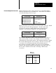
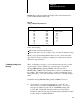
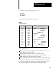
Table 3.K
Display
of Converted Data
Line Conversion Display Notes
1
2
3
4
5
2 ASCII/word
1 ASCII/word
4 Hex/word
4 BCD/word
3 BCD/word
1 2 3 4 A B C D + M 0
2 4 B D + 0
3132 3334 4142 4344 20AB CDEF
3132 3334 4142 4344 20AB CDEF
132 334 142 344 0AB DEF
1
1 2
3
1 2 ASCII/word conversion examines the 7 bit code in each byte: AB=1010101
1=+;
CD=11001
101=M; EF=1
110111
1=o (Note that lower case letters are displayed as upper case
letters.)
2 Bits 1017 are not used in 1 ASCII/word conversion
3 Bits 1417 are not used in 3 BCD/word conversion
Verify the conversions (Table 3.K) as follows:
1. Load the file of the file-to-file move instruction (rung 15) starting at
position 001 exactly as shown in Table 3.J. Use procedure P3 and P5
from “Writing Data to Your ASCII Device”, P. 1-14.
Procedure
P3 Set your industrial terminal to PLC2 mode
Procedure P5 Load data into the filetofile move instruction
2. Set initialization word one to data mode, and select three
initialization words. Set IW1=0002. Use the procedure in section
titled “Setting Bits in Initialization Words”, P. 3-4.
3. Change your data conversion to 2 ASCII characters per word and set
the string length to 12, (IW2=0012).
4. Remove the BCD delimiter from initialization word four. Set
IW4=0000.
5. Change operation of your industrial terminal to alphanumeric mode.
Transfer data to the industrial terminal by changing the processor
mode select switch to the RUN/PROG position.
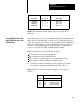
Results The industrial terminal displays
1234ABCD+M0(table 4.K, line1)
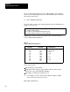
6. Verify the remaining conversions in lines 2, 3, 4 and 5 (Table 3.K) by
setting IW2(16-14) as follows: