
Owner's manual

Choosing Module Features
Chapter 3
39
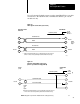
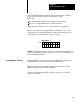
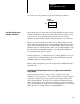
Use a 25-pin male D-shell connector such as Amp DB-25P for your cable
connections to the ASCII module. Terminate the shield to pin 1 at the
module end only.
Figure 2.6
AB
Long Line Connections (5000 ft max)
2
25
3
2
7
11
Receive
Receive
Transmit
Drain Wire (Shield)
To I/O
Chassis
Ground
1
ASCII ModuleIndustrial Terminal
Channel B
18 25
Transmitted Data
Return
Received Data
Return
1
Solder
an external ground wire (14 ga.) to the drain wire at the cable connector
.
Connect it to the I/O chassis ground lug. Ground the shield at this end only
.
11826
Belden
8723 or
Equiv.
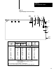
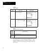
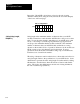
Figure 2.7
RS232C
Simplex W
rite Connections
(Refer to Specifications in Appendix D)
7 7
Receive Transmit
Drain Wire (Shield)
To I/O
Chassis
Ground
[1]
ASCII ModuleDevice
(DTE)
3 3
Signal Ground (AB)
Received Data (BB)
11827
NOTE: Jumper pin 2 to pin 18 at the module end of the cable (special case).
Solder
an external ground wire (14 ga.) to the drain wire at the cable connector
.
Connect it to the I/O chassis ground lug. Ground the shield at this end only
.
(DCE)
2
18
Belden
8723
or
Equiv.
[1]