
Owner's manual


Choosing Module Features
Chapter 3
34
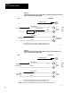
AB Long Line
Use A-B Long Line for communicating up to 5000 cable feet between an
industrial terminal, serving as an ASCII device, and the ASCII module.
Refer to Table 2.D for a detailed listing of A-B Long Line pin functions.
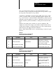
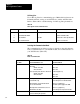
Table 2.D
AB
Long Line Connector Pin Functions
Pin No.
Signal Name
Source Function
2 T
ransmitted Data
AB Long Line Device
Data T
ransfer to 1771DA
7 T
ransmitted Data Return Return for transmitted data
11
Received Data
1771DA
Data transfer to AB Long Line Device
25
Received Data Return
Return for received data
Selecting the Communication Mode
The communication mode that you choose depends on the cable distance
from your ASCII device to your ASCII module, and on characteristics of
your ASCII device (Table 2.E).
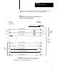
Table 2.E
Mode
of Communication
If Distance is
Less Than
And Y
our ASCII Device is a
Then Choose this
T
ransmission Mode
50 feet
Data T
erminal Equipment (DTE) and conforms
to RS232C
without control lines
with control lines
Data Set (modem) and conforms to RS232C
without control lines
with control lines
RS232C (Figure 2.1)
4wire cable
8wire cable
RS232C (Figure 2.2)
4wire cable
8wire cable
500 feet
DTE and provides a 20mA current source for
the transmit line, only
DTE and requires a 20mA external current
source for its transmit line
DTE and provides 20mA current sources for
transmit and receive lines
Current Loop (Figure 2.3)
The module powers its own transmit line.
Current Loop (Figure 2.4)
Y
ou add the power supply for the DTE.
Current Loop (Figure 2.5)
The module operates in passive transmit.
5000 feet AB industrial terminal or contains a line driver
receiver for AB long line operation.
AB Long Line (Figure 2.6)