
Owner's manual


Choosing Module Features
Chapter 3
32
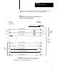
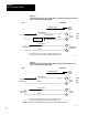
Pin Signal
2
3
4
5
7
transmit
data
receive data
request to send
clear to send
ground
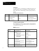
Refer to Table 2.A for a detailed listing of RS-232-C pin functions.
Table 2.A
RS232C
Connector Pin Functions
Pin
No
Signal Name
EIA
Circuit
Source Functions
2 T
ransmitted Data
BA DTE
Data T
ransfer to
1771DA (DCE)
3
Received Data
BB 1771DA
(DCE)
Data T
ransfer to DTE
4
Request to Send
CA DTE T
ells the 1771DA data is
transmitted.
5
Clear to Send
CB 1771DA
(DCE)
T
ells DTE that data is
transmitted. Enabled only
if pin 4 is Vdc (of
f).
6
Data Set Ready
CC 1771DA
(DCE)
T
ells DTE that 1771DA
(DCE) is ready
.
7
Signal Ground
AB
Common ground for all
signals thru interface port
on 1771DA.
8
Receive Line Signal
Detector
CF 1771DA
(DCE)
T
ied to +12V dc
20
Data T
erminal Ready
CD DTE T
ells 1771DA (DCE) that
DTE is ready
. Must be
+V dc to send or receive.
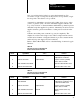
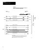
Current Loop
Use the current loop for communicating up to approximately 500 cable
feet between your ASCII device and ASCII module. A current loop has
high immunity to errors caused by electrical noise, has no signal
attenuation, eliminates ground loops, and is low cost.
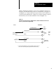
A current loop is a loop that carries current (generally 20mA) between
electronic equipment by means of a twisted pair of wires. A transmitting
device in the loop transmits digital signals by interrupting the current