
Owner's manual
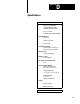

Specifications
Appendix D
D2
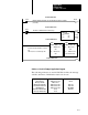
Passive Receive CIrcuit
(pins 12 and 24)
Isolation:
3000Vdc between customer and
PC system circuitry
500V/us common mode
transient immunity
Input Current Range:
4.0mA to 20.0mA for mark state
0.0mA to 0.5mA for space state
Nominal Input Voltage Range:
1.51V @ 4mA to 2.05V @ 20mA
for mark state
0.0V to 1.10V @ 0.5mA for
space state
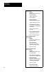
Reverse Input V
oltage Limit:
5.0V between pins 12 and 24
No reverse voltage protection
Active T
ransmitter Circuit
(pins 13 and 1
1)
Isolation:
500Vdc between customer and
PC system circuitry
Input Current Range
:
23.0mA max for mark state
(load must exceed 300 ohms)
0mA for space state
Passive T
ransmitter Circuit
(pins 1
1 and 18)
Isolation:
500Vdc between customer and
PC system circuitry
Device and power supply must
float referenced to module ground
Input Current Range:
55.0mA max for mark state (max
voltage across pins 1
1 and l8 is
2.29, nominal is 1V@20mA)
0mA for space state
Reverse V
oltage Limit:
2.7V across pins 1
1 and 18