
Owner's manual

ASCII Module
For PLC3 Processor
Appendix B
B-20
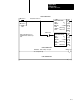
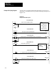
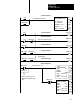
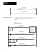
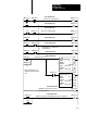
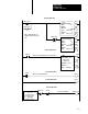
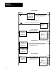
A write (only) program for transferring data from your processor’s
data table to your ASCII device is presented with rung descriptions in
Figure A.19.
Figure B.10
Example
W
rite (Only) Program
00
WO005:0000
00
MOV
MOVE FROM A TO R
A : WO001:0000
0000000000000000
R : WO002:0000
0000000000000000
RUNG NUMBER RM0
Load zeros into command word 1 with
selector switch or on first scan
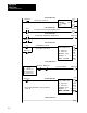
RUNG NUMBER RM1
WO003:0000
07
WO002:0000
07
Power-up/reset power-up initialization bit
WO003:0000
07
S0003
01
WO005:0000
01
L
RUNG NUMBER RM2
WO005:0000
RUNG NUMBER RM3
TON
TIMER ON
1.0 SECOND
TP =
TA =
T0001
2
0
T0001
17
TE
T0001
15
TD
01
Energize at power-up to load initialization words. Also energized on
on 1st scan after processor selection of run monitor mode
Energize timer on power-up
WO005:0000
01
T0001
15
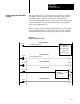
RUNG NUMBER RM4
U
De-energize timer after transferring initialization words
00
WO005:0000
WO002:0000
17
RUNG NUMBER RM5
Command word 1 initialization bit. Module expects
up to 4 initialization words
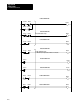
01
I0001
I0001
Example Write (Only) Program