
Owner's manual

ASCII Module
For PLC3 Processor
Appendix B
B-10
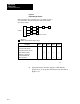
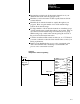
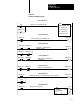
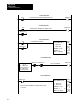
Figure B.3
Diagramming
I/O Channels
Step 1 Diagram the chassis connected in series to each channel (up to four) of
your scanner module. Then, fill in the information called for below. Example
values have been added.
11020
200
310
4Make interactive thru processor LIST
Scanner
= I/O Chassis
Description Number
Active I/O channels
Block Transfer I/O channels
Block Transfer modules on each
I/O block transfer channel
I/O chassis on each block-
transfer I/O channel (I/O
chassis in rack list)
Ch 1 Ch 2 Ch 3 Ch 4
3
2
3
4
0
0
1
2
0
0
12828
n = number of blocktransfer modules in chassis
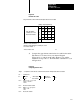
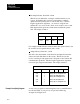
2. Using information from the diagram of I/O channels
(Figure A.12), look up the nominal time from the table in
Figure A.13.