
Owner's manual

ASCII Module
PLC-2 Family Processors
Appendix A
A7
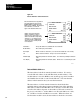
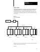
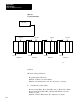
Figure A.3
Example
Data Table Locations for Bidirectional Block T
ransfers
1
R
Block length code
Data Table
130
010
013
040
Output image table low
byte
Data Addresses contains module
address 130: rack 1, module group 3,
slot 0.
Input image table low byte
R = Read bit
W = Write bit
EN
BLOCK XFER READ
DATA ADDR:
MODULE ADDR:
BLOCK LENGTH:
FILE:
040
130
00
300- 347
DN
013
07
113
07
113
1
W
130
1
RW
1
1
R
1
W
041
3 0 0 140
400
141
Storage locations of file addresses
300
347
400
447
Read Block Transfer File
Write Block Transfer File
Read block transfer file length set to
00, which allows a 64 word transfer
Write block transfer file length set to
00, which allows a 64 word transfer
EN
BLOCK XFER WRITE
DATA ADDR:
MODULE ADDR:
BLOCK LENGTH:
FILE:
041
130
00
400- 447
DN
013
06
113
06
11839
~~
~
~
~
~
~
~