
Owner's manual

Function of Control/Status Bits
Chapter 6
623
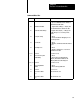
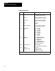
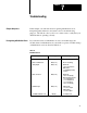
Status Word One
Bit Function Status*
17 Channel
Active
0 = Reset
1 = The ASCII device is enabled
16 W
rite Data
Acknowledge
Module toggles SW1(16)=CW1(16) to tell
PC that new data was received
15
Read Data A
vailable
Module toggles SW1(15)
≠
CW1(15) when
it detects a change in status or receives
new data from ASCII device
14
Input String Exceeds
Maximum
0 = Reset
1 = Input string >set string length in
IW2(0013)
13
ASCII Device/Link
Error
0 = Reset
1 = Module detects parity, framing or
overrun error in string from the ASCII
device
12
Initialization Error
0 = Reset
1 = Module ceases to operate
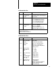
11
Not Used Module sets it to zero
10
Data Complete
0 = Reset
1 = Module detects delimiter at end of
string that is distributed over one or
more block transfers.
07 Powerup
Initialization
0 = Reset by CW1(07)
1 = Powerup initialization is complete
06
Not used
Module sets it to zero
05
Output Buf
fer Full
0 = Reset when less than full
1 = Output buf
fer full
04
Output Buf
fer Empty
0 = Reset when data enters buf
fer
1 = Output buf
fer empty
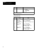
03
Input Buf
fer full
0 = Reset by CW1(03) when input buf
fer is
empty
1 = Input buf
fer is full
02
Input Buf
fer 75% Full
0 = Reset when less than 75% full
1 = Input buf
fer is 75% full
01
Input Buf
fer 50% Full
0 = Reset when less than 50% full
1 = Input buf
fer is 50% full
00
Input Buf
fer Empty
0 = Reset when data enters buf
fer
1 = Input buf
fer is empty
*The module sets these bits (unless toggled) when it detects the subject condition.