
Owner's manual

ASCII I/O Module Tutorial
Chapter 4
451
Verify that this message file will display the diagnostic codes as shown.
1. Set your initialization words as follows:
RG mode, 4 initialization words, 300 baud IW1 = 0007
4 BCD characters/word, 32 characters/string IW2 = 2032
End-of-string delimiter is a carriage return IW3 = OD00
BCD delimiter is a colon (:) IW4 = 3A00
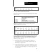
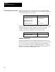
Display The initialization word file is displayed in hex as follows:
RADIX
= %H ST
AR
T = WO007:0000
WORD
#
00000
0
0000
1
0000
2
0007
3
2032
4
0D00
5
3A00
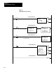
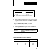
2. Writing over the previous data, load the message into file O6:0 (hex
display) as shown above. Load diagnostic codes into display words
6 and 7; 14 and 15; 22 and 23.
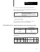
Refer to procedures P3 and P5 from section titled “Writing Data To Your
ASCII Device” (chapter 1).
Procedure
P3
Connect the 1775CA
T cable, and set the industrial terminal
to PLC3 mode
Procedure P5
Load data into the file O6:0
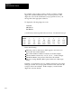
3. Transfer your message for display on the industrial terminal. Refer
to the procedures in section titled “Writing Data to Your ASCII
Device” (chapter 1).
Procedure
P1
Connect the 1770CB cable, and set the industrial terminal
to alphanumeric mode (check parameters)
Procedure P6
Enable the MVF instruction. With the PLC3 in run monitor
,
enter I001:04 and enable that bit; then I001:02 and enable
that bit (in that order)
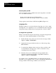
Results The industrial terminal displays the column of diagnostic codes
at the left of the screen.
123245678
ABCD4321
FACEBAC2