
Owner's manual

ASCII I/O Module Tutorial
Chapter 4
447
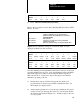
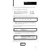
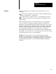
RADIX
= %H ST
AR
T = WO007:0000
WORD #
00000
0
0000
1
0000
2
0007
3
2021
4
0D00
5
2F00
2. Enter: PRODUCED/0000/PARTS[ENTER]
Refer to the procedures in section titled “Reading Data From Your ASCII
Device” (P. 1-28).
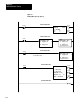
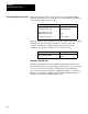
Procedure
P1
Connect the 1770CB cable, and set your industrial
terminal to alphanumeric mode (check parameters)
Initialize the module by changing PLC3 operation mode
3[ENTER]2[ENTER]
Procedure P2
Enter your data
Procedure P3
Connect the 1775CA
T cable, and set your industrial
terminal to PLC3 mode
Procedure P4
Observe how the data string is stored in data table file O6:0
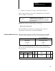
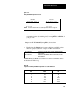
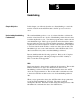
Display Your 21 character message is stored in file O6:0. You can
display it in ASCII or in hex as follows:
RADIX
= %A ST
AR
T = WO006:0000
WORD #
00000
0
00H00H
1
00H00H
2
P R
3
O D
4
U C
5
E D
6
/
7
00H00H
00010 /
P A
R T
S 00H
00H00H 00H00H 00H00H 00H00H
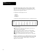
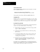
RADIX = %H ST
AR
T = WO006:0000
WORD #
00000
0
0000
1
0000
2
5052
3
4F44
4
5543
5
4544
6
202F
7
0000
00010 2F20 5041 5254 5300 0000 0000 0000 0000
Store the delimiter preceding the BCD value in the lower byte of the word
preceding the BCD storage word. Store the delimiter following the BCD
value in the upper byte of the word following the BCD storage word.
This is shown above. If necessary, add an extra space before the first
delimiter to properly position it.
3. Identify the storage word in the message file into which your
program will move the message variable (accumulated value). In
this example, it is display word 7.
4. Add program logic that moves your message variable into the proper
storage word in your message file, and moves your message file into
the write block transfer file (Figure 3.9). Add these rungs to the end
of your program.