
Owner's manual

Getting Started with Your ASCII Module
Chapter 2
25
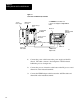
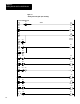
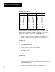
Figure 1.2
Connections
for PLC2/20 or PLC2/30 Controller
ModuleGroup1,
Slot1
1771-ALLocal
AdapterModule
1771-A1,-A2,-A4
I/OChassis
1771-DAASCII
I/OModule
1771-CK,-CJ
PowerCable
1770-T3
IndustrialTerminal
(rearview)
ChannelA
ChannelB
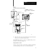
11818
PLC-2/30
Processor
1770-CBIT/DH
AdapterCable
1771-CA,-CB
I/OInterconnect
Cable
1772-TCProcessor
InterfaceCable
1777-CP
TerminationPlug
See WARNING in section titled How
to Connect Your Equipment." Using Channels
A & B
4. (PLC-2/20, -2/30, only) Connect the I/O interconnect cable between
the PC processor and the I/O adapter module
If the IT/DH adapter cable is too short or not available, make your own.
It should not exceed 50 feet (Figure 1.4).
Using Channels A and B
You may or may not be able to connect cables to channels A and B at the
same time depending on the revision of your industrial terminal.