Allen Bradley ASCII I/O Module (Cat. No.
Table of Contents To Our Customers . . . . . . . . . . . . . . . . . . . . . . . . . . . . . . . 1 1 Overview of This Manual . . . . . . . . . . . . . . . . . . . . . . . . . . . . . . Intended Audience . . . . . . . . . . . . . . . . . . . . . . . . . . . . . . . . . . . Notational Conventions . . . . . . . . . . . . . . . . . . . . . . . . . . . . . . . . Some Tips on Using This Manual . . . . . . . . . . . . . . . . . . . . . . . . Typical Applications . . . . . . . . . . . . . . . . . . . . . . . . .
ii Table of Contents ASCII I/O Module Tutorial . . . . . . . . . . . . . . . . . . . . . . . . . . 4 1 Chapter Objectives . . . . . . . . . . . . . . . . . . . . . . . . . . . . . . . . . . . PLC 2 Family Processors . . . . . . . . . . . . . . . . . . . . . . . . . . . . . . Adding Initialization Rungs . . . . . . . . . . . . . . . . . . . . . . . . . . . . . Setting Bits in Initialization Words . . . . . . . . . . . . . . . . . . . . . . . . Expanding the Number of Initialization Words . . . . . . . .
Table of Contents iii Troubleshooting . . . . . . . . . . . . . . . . . . . . . . . . . . . . . . . . 7 1 Chapter Objectives . . . . . . . . . . . . . . . . . . . . . . . . . . . . . . . . . . . Recognizing Initialization Errors . . . . . . . . . . . . . . . . . . . . . . . . . . How You Interpret Status Indicators . . . . . . . . . . . . . . . . . . . . . . . How You Interpret Codes in Status Word One . . . . . . . . . . . . . . . . Testing the ASCII Module and Cables . . . . . . . . . . . . . . . . .
Preface To Our Customers Overview of This Manual This manual tells you in a tutorial manner how to install and use your ASCII module.
Preface To Our Customers A symbol or word in brackets represents a single key you would press. These include keys such as [ENTER], [SHIFT], or [ ]. Spaces would be entered as shown, except that the space preceding and following the brackets is not an entered space. (We put a space before the left bracket and after the right bracket to make it easier to read). Numbers and capital letters not in brackets would be entered as shown. Punctuation such as commas, and symbols such as / would be entered as shown.
Preface To Our Customers You will use several procedures frequently in the tutorial chapters of this manual.
Chapter 2 Getting Started With Your ASCII Module ASCII is the acronym for American Standard Code for Information Interchange. The standard includes a 7-bit code for 128 data and control characters. With your ASCII I/O module you can transfer data, by means of the I/O scan, from an ASCII device to the PC processor data table, and vice versa. The module has two modes of operation, data mode and report generation mode. In data mode, you can transfer ASCII, BCD, or hex characters.
Chapter 2 Getting Started with Your ASCII Module PLC 2 Family Processors What You Need to Get Started You will demonstrate the operation of your ASCII module by reading data from the industrial terminal to the processor data table, and by writing data from the data table to the industrial terminal. You will use your industrial terminal as an ASCII device for entering data (read), and for displaying data (write).
Chapter 2 Getting Started with Your ASCII Module or Processor Mini PLC 2/15 Power Supply 1771 P1 Power Cable 1771 CL Note: You must use battery back-up. The ASCII module draws 1.3A from the backplane. Be sure that the total current drain of all modules in the chassis does not exceed the maximum for the backplane and power supply. If you use an existing system, consider disconnecting all other chassis except the one containing your ASCII module.
Chapter 2 Getting Started with Your ASCII Module Figure 1.1 Connections for Mini PLC 2/l5 Controller 1771-P1 Power Supply Mini-PLC-2/15 Processor Module Group 1, Slot 1 See WARNING in section titled How to Connect Your Equipment." Using Channels A&B Channel A 1770-T3 Industrial Terminal (rear view) 1771-DA ASCII I/O Module 1771-A1, -A2, -A4 I/O Chassis 1772-TC Processor Interface Cable Channel B 1771-CL Power Cable 2 4 1770-CB IT/DH Adapter Cable 11817 1.
Chapter 2 Getting Started with Your ASCII Module Figure 1.2 Connections for PLC 2/20 or PLC 2/30 Controller PLC-2/30 Processor See WARNING in section titled How to Connect Your Equipment.
Chapter 2 Getting Started with Your ASCII Module Industrial terminals manufactured before May 1982 allow cross talk between channels A and B. As a result, data table values could be altered. Therefore, you should alternate cables between channels for the tutorials of this manual when using these terminals. When using a series A industrial terminal, you must alternate cables. Your industrial terminal has a date code stamped in white on the upper right corner of the rear label.
Chapter 2 Getting Started with Your ASCII Module 2. Locate the programming plugs and set them according to RS-232-C without control lines (figure 2.8). Entering the ““Getting Started Program”” You may want to record on tape the ladder diagram of your application program before proceeding because you will need to load ASCII logic into a cleared memory for chapters 1 and 3. Using your industrial terminal, enter the ““Getting Started Program”” (Figure 1.3) into processor memory.
Chapter 2 Getting Started with Your ASCII Module Figure 1.3 Getting Started Program" (PLC 2 Family) LADDER DIAGRAM DUMP 327 020 G 000 02 252 07 020 START 200 PUT 000 200 07 063 TON 063 063 .
Chapter 2 Getting Started with Your ASCII Module 011 BLOCK XFER READ DATA ADDR: 030 MODULE ADDR: 111 BLOCK LENGTH: 16 FILE: 252 - 271 EN 17 111 DN 17 011 BLOCK XFER WRITE DATA ADDR: 031 MODULE ADDR: 111 BLOCK LENGTH: 16 FILE: 200 - 217 EN 16 111 DN 16 020 END 00460 02 NOTE: Configure the data table for two racks using [SEARCH][5][0] before entering this program.
Chapter 2 Getting Started with Your ASCII Module BUFFER FULL: Normally off. This yellow LED indicator illuminates when the input buffer becomes full. CHANNEL ACTIVE: This green LED indicator illuminates when the industrial terminal is on, properly connected to the ASCII module’s interface port, and set for alphanumeric mode. Reading Data from Your ASCII Device In this demonstration, you will enter data and observe how it is stored in the processor data table.
Chapter 2 Getting Started with Your ASCII Module To avoid switching keytop overlays every time you change the industrial terminal operating mode, you can label numbers, letters, and [RETURN] on the corresponding keytops of the PLC-2 family overlay. 3. Select alphanumeric mode. Press 12 on the keyboard The ASCII module’s CHANNEL ACTIVE LED illuminates. 4. Set the communication rate to 300 baud.
Chapter 2 Getting Started with Your ASCII Module Table 1.B Commonly Used Data Characters ASCII Hex space 0 1 2 3 4 5 6 7 8 9 20 30 31 32 33 34 35 36 37 38 39 ASCII A B C D E F G H I J K L M Hex 41 42 43 44 45 46 47 48 49 4A 4B 4C 4D ASCII N O P Q R S T U V W X Y Z Hex 4E 4F 50 51 52 53 54 55 56 57 58 59 5A The industrial terminal displays the characters as you enter them. If characters are not displayed, check the program that you loaded into memory.
Chapter 2 Getting Started with Your ASCII Module Press [DISPLAY] 1 Results The industrial terminal displays the name and numbers (first 10 characters) that you entered in step 2. For example, ALLEN 12345 would be displayed as: POSITION FILE DATA ASCII Equivalent 001 E010 status word one 002 0000 status word two 003 414C A L 004 4C45 L E 005 4E20 N 006 3132 1 2 007 3334 3 4 Entering the eleventh character caused the module to transfer the data.
Chapter 2 Getting Started with Your ASCII Module If you are still having trouble, refer to “Testing the ASCII Module and Cables,” to verify communication between the ASCII module and the industrial terminal. If you suspect a cable problem, check the 1770-CB cable (Figure 1.4). Then try again, starting at Procedure P1. Figure 1.
Chapter 2 Getting Started with Your ASCII Module You will use the following procedures where Procedures P1 and P3 are repeated from the section titled Reading Data from Your ASCII Device.
Chapter 2 Getting Started with Your ASCII Module For example, load the following hex codes that are equivalent to BRADLEY 12345 as follows: (Note the space between BRADLEY and 12345.) POSITION FILE DATA ASCII Equivalent 003 4252 B R 004 4144 A D 005 4C45 L E 006 5920 Y 007 3132 1 2 008 3334 3 4 009 3500 5 Check your display of FILE DATA to be sure that you entered all data exactly as shown. Don’t forget to press [INSERT][ ] after entering data in each position.
Chapter 2 Getting Started with Your ASCII Module Results The following display appears at the upper left corner of the industrial terminal: BRADLEY 12345 5. Terminate the display and return to ladder diagram. Use the PLC-2 family keytop overlay. Press [MODE SELECT] 11 Summary Now that you have demonstrated the transfer of data from your ASCII device to the data table and vice versa, you are ready to use these procedures further. First, read the next chapter, “Choosing Module Features.
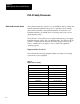
Chapter 2 Getting Started with Your ASCII Module PLC 3 Processors What You Need To Get Started You will demonstrate the operation of your ASCII module by reading data from the industrial terminal to the processor data table, and by writing data from the data table to the industrial terminal. You will use your industrial terminal as an ASCII device for entering data (read), and for displaying data (write).
Chapter 2 Getting Started with Your ASCII Module Table 1.
Chapter 2 Getting Started with Your ASCII Module How to Connect Your Equipment Connect your equipment using the appropriate cables (Figure 1.5). Figure 1.
Chapter 2 Getting Started with Your ASCII Module 2. Connect the I/O power cable between the power supply and the I/O chassis. 3. Connect the twin axial cable between the I/O scanner in the processor chassis and the remote I/O adapter module in the I/O chassis (Figure 1.6). Figure 1.6 Twinaxial Cable Terminations Terminals on I/O Scanner Module Channel No. 3 Blue Channel No. 1 Line 1 Line 1 Shield Shield Line 2 Line 2 Channel No. 4 Line 1 Shield Clear Shield Line 2 Channel No.
Chapter 2 Getting Started with Your ASCII Module 5. Connect the IT/DH adapter cable between the ASCII module and channel B of the industrial terminal. Channel B Periodically you will have to switch the cables that connect to channel B of the industrial terminal. You will use the industrial terminal cable (cat. no. 1775-CAT) when using the industrial terminal in PLC-3 mode and entering or displaying data in the PLC-3 data table. You will use the IT/DH adapter cable (cat. no.
Chapter 2 Getting Started with Your ASCII Module Refer to your PLC-3 Programmable Controller Installation and Operation Manual (publication 1775-800) for additional installation information such as switch settings for the adapter module and I/O chassis, and for grounding information. Checking ASCII Module Configuration Your module is configured for RS-232-C operation when shipped from the factory.
Chapter 2 Getting Started with Your ASCII Module Figure 1.
Chapter 2 Getting Started with Your ASCII Module RUNG NUMBER RM10 WB004:0000 BTR BLOCK XFER READ 001 RACK : 1 GROUP : 1=HIGH MODULE : DATA : FO003:0000 0 LENGTH = FB004:0000 CNTL : 15 WB004:0000 05 WB004:0000 17 BTW BLOCK XFER WRITE 001 RACK : 1 GROUP : MODULE : 1=HIGH DATA : FO002:0000 0 LENGTH = FB004:0000 CNTL : RUNG NUMBER RM11 CNTL EN 12 CNTL DN 15 CNTL EN 13 CNTL EN 02 CNTL DN 05 CNTL ER 03 WO005:0000 00 1. Connect the 1775-CAT cable to channel B of the industrial terminal. 2.
Chapter 2 Getting Started with Your ASCII Module The displayed power bars will be replaced by I’s at the left and right margins of the screen. The prompt EDITING will blink. 7. Enter your instructions and addresses. Refer to the PLC-3 Programming Manual (publication 1775-801) as needed. NOTE: Be sure that you have entered the prefix F (file) in the addresses of your block transfer read (BTR) and block transfer write (BTW) instructions.
Chapter 2 Getting Started with Your ASCII Module the rack, group, and slot number of the module address in the block transfer read and write instructions, accordingly.) 3. Turn on power to the I/O chassis. Three LED indicators on the ASCII module illuminate momentarily. Their functions are: FAULT: Normally off. This red LED indicator illuminates when the module detects an internal fault. BUFFER FULL: Normally off. This yellow LED indicator illuminates when the input buffer becomes full.
Chapter 2 Getting Started with Your ASCII Module Reading Data from Your ASCII Device In this demonstration you will enter data and observe how it is stored in the processor data table. You will use the industrial terminal in alphanumeric mode as an ASCII data terminal when you enter data. Then you will change the industrial terminal to PLC-3 mode and observe the transferred data by displaying the contents of the block transfer read file.
Chapter 2 Getting Started with Your ASCII Module 4. Set operating parameters: Communication rate to 300 baud. Press A (as needed) until the communication rate, as displayed on the screen, reaches 300 baud. Hardware handshaking to ON. Press D DUPLEX to FULL. Press F B and C to any setting. E, and G thru M to OFF. Press [ENTER] to load parameters. The prompt, ENTERING ALPHANUMERIC TERMINAL MODE, tells you the terminal is ready for your input. Procedure P2 Enter Your Data 1.
Chapter 2 Getting Started with Your ASCII Module ASCII Hex ASCII Hex ASCII Hex 8 38 J 4A W 57 9 39 K 4B X 58 L 4C Y 59 M 4D Z 5A The industrial terminal displays the characters as you enter them. If characters are not displayed, check the program that you loaded into memory. Check step 3, operating parameters, for errors. If you find no errors, refer to Need Help? below. Procedure P3 Set Your Industrial Terminal to PLC-3 Mode 1. Connect the 1775-CAT cable to channel B. 2.
Chapter 2 Getting Started with Your ASCII Module 2. Display the same file in hex. Press,%H [ENTER] The following display appears: RADIX = %A START = WA011:0248 WORD # 0 1 2 3 4 5 6 7 00000 E011 0000 4153 4349 4920 3738 3930 0000 3. You can display the file in other number bases by replacing the H in step 2 with D for decimal, B for binary, or A for ASCII. Compare the following displays.
Chapter 2 Getting Started with Your ASCII Module If you are still having trouble, refer to “Testing the ASCII Module and Cables,” to verify communication between the ASCII module and the industrial terminal. If you suspect a cable problem, check the 1770-CB cable (Figure 1.7). Then try again starting with Procedure P1. Writing Data to Your ASCII Device In this demonstration you will load data characters into the write block transfer file and observe how they are displayed by the industrial terminal.
Chapter 2 Getting Started with Your ASCII Module Press [SHIFT][LIST]3[ENTER] 2. Display the file that you want to load by entering the address of that file (O2:0) with the following key sequence. Press DD,O2:0,[SHIFT]%A[ENTER] 3. Load ASCII data into the file starting with the third word (display word 2) for block transfer instructions (the first word for file move instructions). The first and second words of a write block transfer instruction are reserved for command words (handshaking).
Chapter 2 Getting Started with Your ASCII Module 1. Connect the 1770-CB cable to channel B. 2. Select alphanumeric mode. Press [SHIFT][MODE]2 3. Check operating parameters: Communication rate is 300 baud. Hardware handshaking is ON. DUPLEX is FULL. B and C are any setting. E, and G thru M are OFF. Press [ENTER] to load parameters. The module’s CHANNEL ACTIVE LED turns on. 4. Change the operation of your PC-3 controller to run monitor from the PLC-3 front panel.
Chapter 2 Getting Started with Your ASCII Module BRADLEY 12345 at the upper left corner of the screen. 3. Reset the bit using the PLC-3 front panel. Press 0 [ENTER] 4. Terminate the display and return to ladder diagram by connecting the 1770-CB cable to channel B, and entering the following keystrokes on the industrial terminal keyboard.
Chapter 3 Choosing Module Features Chapter Objectives Because of the many types of ASCII devices available and the variety of possible applications, you must configure your module according to the ASCII device and specific application that you have chosen. To do this, you must make some decisions. We will show you how to configure your module using programming plugs and by setting bits in initialization words.
Chapter 3 Choosing Module Features Pin Signal 2 3 4 5 7 transmit data receive data request to send clear to send ground Refer to Table 2.A for a detailed listing of RS-232-C pin functions. Table 2.A RS 232 C Connector Pin Functions Pin No Signal Name EIA Circuit Source Functions 2 Transmitted Data BA DTE Data Transfer to 1771 DA (DCE) 3 Received Data BB 1771 DA (DCE) 4 Request to Send CA DTE Tells the 1771 DA data is transmitted.
Chapter 3 Choosing Module Features flow. A receiving device in the loop senses the interruptions. By convention, a logic 1 corresponds to the presence of loop current; a logic 0 corresponds to the absence of loop current. A current loop transmitter or receiver can be either of two types: active (source) or passive (sink). An active transmitter supplies current to the loop. Any receivers or other transmitters within that loop must be passive units that accept the supplied loop current.
Chapter 3 Choosing Module Features A B Long Line Use A-B Long Line for communicating up to 5000 cable feet between an industrial terminal, serving as an ASCII device, and the ASCII module. Refer to Table 2.D for a detailed listing of A-B Long Line pin functions. Table 2.D A B Long Line Connector Pin Functions Pin No.
Chapter 3 Choosing Module Features The functions of the cable conductors (Figure 2.1 thru Figure 2.7) are referenced to your ASCII device, not to your ASCII module. Figure 2.1 RS 232 C Connections (50 ft.
Chapter 3 Choosing Module Features Figure 2.2 RS 232 C Connections (50 ft. max): Data Set to Data Set (Refer to specifications in Appendix D) Device Data Set (DCE) ASCII Module (DCE) To I/O Chassis Ground 2 Drain Wire (Shield) 2 Receive 7 Transmit 3 4 5 Control Lines 6 8 20 Received Data (BB) 2 7 Transmit Transmitted Data (BA) 3 Request to Send (CA) Belden 8778 or Equiv. 4 Clear to Send (CB) 5 Data Set Ready (CC) Received Line Signal Detector Belden 8723 or Equiv.
Chapter 3 Choosing Module Features When configured for current loop and you use terminals 13 and 11 for transmit, your ASCII module powers its own transmit loop (Figure 2.3 and Figure 2.4). Your module can accept an active receive current loop powered by the ASCII device. In this case, module operation is passive transmit and you use module terminals 11 and 18 (Figure 2.5). Figure 2.3 Current Loop Connections (500 ft.
Chapter 3 Choosing Module Features Figure 2.4 Current Loop Connections (500 ft. max): Device is Passive Transmit, Passive Receive (Refer to specifications in Appendix D) Device ASCII Module To I/O Chassis Ground 1 Drain Wire (Shield) Transmitted Data 12 4-20mA mark state Passive Transmit + Power Supply Return - Received Data 24 13 Passive Receive Return 11 (+) Passive Receive (-) Belden 8723 or Equiv. (+) Transmit with Current Source (-) 1 Solder an external ground wire (14 ga.
Chapter 3 Choosing Module Features Use a 25-pin male D-shell connector such as Amp DB-25P for your cable connections to the ASCII module. Terminate the shield to pin 1 at the module end only. Figure 2.6 A B Long Line Connections (5000 ft max) Industrial Terminal Channel B ASCII Module To I/O Chassis Ground 1 Drain Wire (Shield) Transmitted Data 2 2 Return 25 7 Received Data 3 Receive 11 Transmit Return 18 Receive Belden 8723 or Equiv. 25 1 Solder an external ground wire (14 ga.
Chapter 3 Choosing Module Features Setting the Module's Programming Plugs Implement your choice of cable configuration by setting programming plugs inside the module. Remove the module’s left-hand cover plate (the one without the labels). Locate and adjust the programming plugs according to Figure 2.8. NOTE: The locations of programming plug sockets (Figure 2.8) are labeled El thru E16 on the printed circuit board.
Chapter 3 Choosing Module Features Figure 2.
Chapter 3 Choosing Module Features Setting and Recording Initialization Words The remaining features are configured by using initialization words. These words are write block transferred to the module at power-up or upon command. You will record your selections of module features by writing codes (0 or 1) for corresponding initialization bits. You can do this with either of the initialization word forms at the end of this chapter.
Chapter 3 Choosing Module Features Choosing the Mode of Module Operation, IW1(02 04) The mode of module operation that you choose depends on the application and type of ASCII device. Typically, use data mode when you are reading data from an ASCII device, such as a bar code reader. Use report generation mode when you are writing messages to an ASCII data terminal (Table 2.F). Table 2.
Chapter 3 Choosing Module Features Choosing Data Conversion, IW2(14 16) Data conversion refers to the number and type of characteers that you store in a data table. word. The selections of data conversion from which you choose depend on the mode of module operation (Table 2.G). Table 2.G Data Conversion When In Select One Using Code Data mode, you must select one type of data conversion (quantity and type of characters per word). To change data conversion, you must reinitialize the module.
Chapter 3 Choosing Module Features Select the BCD delimiter from the following hex characters:: 0A-0F, 1A-1F, 2A-2F, 3A-3F, 4A-4F, 5A-5F, 6A-6F, or 7A-7F. Do not use: Any character that otherwise would appear in the message The end-of-string delimiter that you will select later ASCII characters and their codes are listed in tables in appendix C.
Chapter 3 Choosing Module Features Table 2.H Margin Justification When Justified Left Each New Line Is Displayed with the Same Left margin Example: Text is left justified. and Data Is Stored in the Data Table by Placing The first character in the upper byte of the lowest word address. Blanks or zeros fill the higher word addresses.
Chapter 3 Choosing Module Features If you choose report generation mode, the module ignores this bit. Margin Justification IW3 Using the End of String Delimiter, IW3(10 16) 03 When the module encounters the end-of-string delimiter in data received from the ASCII device, the module allows the read block transfer of data to the processor. If your ASCII device generates an end-of-string delimiter, use that delimiter. (Refer to the specifications of your device.
Chapter 3 Choosing Module Features Record the 7-bit ASCII code in binary or hex for the end-of-string delimiter in IW3(10-16) using the form (found at the end of this chapter) or the boxes on the next page. End-of-String Delimiter IW4 17 16 15 14 13 12 11 10 0 Setting String Length, IW2(00 13) String length is the maximum number of characters that your ASCII module can transfer as a unit from the ASCII device to the processor data table.
Chapter 3 Choosing Module Features Table 2.
Chapter 3 Choosing Module Features Determining Block Transfer Length The highest number of words that you can transfer in one block transfer is 64. You must include two command words in each write block transfer and two status words in each read block transfer in addition to your data words. You can also transfer up to four initialization words (Figure 3.9). Figure 2.
Chapter 3 Choosing Module Features Compute block length by dividing the number of data characters in the longest string length by the type of data storage, i.e. 1, 2, 3, or 4 characters per word. For example, a string of 80 data characters having 2 ASCII characters per word, data storage would require a block transfer block length of 42 words. Don’t forget to add two status words or two command words.
Chapter 3 Choosing Module Features The module would remove the fill character and store the data as follows (assume right justified data, a string length of 11, and two ASCII characters per word). First Transfer Second Transfer 2020 2020 2020 2020 2031 2020 3332 2020 3536 3735 3938 3931 The module removed the fill characters inserted by the device (2D hex), right justified the data, and added its own fill character (20 hex).
Chapter 3 Choosing Module Features inserts a space (20 hex) for one ASCII or two ASCII characters per word conversion, or it inserts a zero (00 hex) for BCD and hex data conversion. The module also adds a fill character to justified BCD data. The fill character that it inserts is a zero for each missing digit. The module also inserts zeros leading a BCD number, if necessary, to align the BCD number on a word boundary (right justified).
Chapter 3 Choosing Module Features Choosing I/O Buffer Size, IW3(00 02) Your ASCII module has a 1536 word (3072 byte) buffer for I/O data. The percentage of buffer memory that you choose for input and output depends on the operation of your ASCII device, and on relative transmission rates into and out of the ASCII module’s I/O buffer. You should proportion the size of your input and output buffers for maximum storage (Table 2.
Chapter 3 Choosing Module Features Choosing Transmission Mode, IW1(05 07) The transmission mode that you choose is determined by the specifications of your ASCII device and the requirements of your application (Table 2.L). Table 2.
Chapter 3 Choosing Module Features Record your choice by writing a 0 (single transfer) or 1 (multiple transfer) in IW2(17). Use the form (found at the end of this chapter) or the boxes below. Single or Multiple Transfers 17 IW2 Selecting Delay for Carriage Return, IW3(06 07) When using an unbuffered data terminal, select a time for the ASCII module to delay outputting data while the mechanical carriage return is operating.
Chapter 3 Choosing Module Features Communication Rate Match the communication rate of your ASCII module with that of your ASCII device. Set bits IW1(10-12) accordingly. Your selections are: Communication Rate Code 300 baud 000 600 baud 001 1200 baud 010 2400 baud 011 4800 baud 100 9600 baud 101 110 baud 110 Number of Data Bits Your ASCII device generates either seven or eight data bits per character (Figure 2.11).
Chapter 3 Choosing Module Features Parity Your ASCII device generates either odd, even, or no parity bit with each character (Figure 2.12). Use the default value (no parity) if this information is not available. Set bits IW1(14,15) accordingly. Figure 2.
Chapter 3 Choosing Module Features Record features that apply to your ASCII device by writing a 0 or 1 in corresponding bits IW1(10-17) using the form (found at the end of this chapter) or the boxes below.
Chapter 3 Choosing Module Features Recording Bit Settings in Initialization Words The next two pages are forms for recording bit settings in the four initialization words. Form 5l75 is for data mode operation of your module; form 5176 for report generation mode. Copy these forms and use them to record your selections of module features. You will use the information that you record on these forms in chapter 3 to set bits in initialization words and to demonstrate the features that you have selected.
Chapter 3 Choosing Module Features Form 5175 Initialization Words for Data Mode IW1 Record Your Selections 17 ACK NAK 16 Stop Bits 15 Parity Enable 14 Parity Odd, even 13 No.
Chapter 3 Choosing Module Features Form 5176 Initialization Words for Report Generation Mode IW1 Record Your Selections 17 ACK NAK 16 Stop Bits 15 Parity Enable 14 Parity Odd, even 13 No.
Chapter 4 ASCII I/O Module Tutorial Chapter Objectives You will use three general procedures in this tutorial. Setting bits in your initialization words Reading data from your industrial terminal Writing data to your industrial terminal You will observe the results of setting bits in your initialization words by reading data from or writing data to your ASCII device. The procedures for reading and writing data were covered in chapter 1.
Chapter 4 ASCII I/O Module Tutorial PLC 2 Family Processors Adding Initialization Rungs You must add initialization rungs to your “Getting Started Program”. Place the processor mode select switch in the PROG position and insert the additional rungs exactly as shown (Figure 3.1). To insert one or more rungs into your program, place the cursor on the output instruction in the previous rung. Press [INSERT][RUNG], then enter the instructions for one rung.
Chapter 4 ASCII I/O Module Tutorial 8 035 252 00 035 15 252 00 063 G 000 020 15 251 = 100 200 L OFF 15 200 U OFF 15 9 10 11 12 13 14 15 01 063 G 000 020 247 = 200 252 01 020 16 252 01 020 16 020 020 00 01 020 L OFF 00 020 L OFF 00 200 L ON 16 200 U FILE TO FILE MOVE COUNTER ADDR: 060 POSITION: 001 FILE LENGTH: 020 FILE A: 400 - 423 FILE R: 202 - 225 RATE PER SCAN: 020 01 16 BLOCK XFER READ 030 DATA ADDR: MODULE ADDR: 111 BLOCK LENGTH: 16 FILE: 252 - 271 17 BLOCK XFER WRITE 031
Chapter 4 ASCII I/O Module Tutorial Setting Bits in Initialization Words Set bits in your initialization words to select desired module features as follows: 1. Place the cursor on the file-to-file move instruction in rung 18. It contains the file of initialization words. 2. Display the file. Press [DISPLAY]1 for hex, or [DISPLAY] 0 for binary.
Chapter 4 ASCII I/O Module Tutorial Expanding the Number of Initialization Words The module has four words that you use to select operating features. You do this by setting one or more bits for each feature that you want to use. You increase the number of initialization words according to the module features that you want to use. For example, if you want a feature that is selected in initialization word three, you must use initialization words one, two, and three. 1.
Chapter 4 ASCII I/O Module Tutorial 2. Demonstrate the string length by entering 16 data characters. When you enter the 16th data character, the module transfers the string of 15 characters to the read block transfer file in the data table, where you can observe it. (The sixteenth character is not transferred but remains as the first character in the input buffer.) Do the following example where the processor will read data from your ASCII module.
Chapter 4 ASCII I/O Module Tutorial Initialization Error If the characters were not displayed when you entered them (ALLEN-BRADLEY 12), and the display of transferred data contained only the code X4XX in status word one, you have an initialization error. (X is any value.) Repeat the procedure in section titled “Setting Bits in initialization Words” (P. 3-4), exactly as shown setting IWl (00-01)=10 in binary or 2 in hex. A setting of IW1 (00-01)=11 in binary or 3 in hex will not work in this example.
Chapter 4 ASCII I/O Module Tutorial Display Your file-to-file move instruction displays your setting as follows: File Data POSITION Hex 003 2. 0008 Binary 00000000 000010000 Repeat step 2 of section titled “Changing the String Length.” Results The read block transfer file displays the 15 data characters in positions 003 thru 010 with the data left justified (Table 3.C). Table 3.
Chapter 4 ASCII I/O Module Tutorial Table 3.D String Length, Right Justified 2. POSITION FILE DATA 001 002 003 004 005 006 007 008 2020 2020 2020 2020 2042 5241 444C 4559 ASCII Equivalent B R A D L E Y Display the data on your industrial terminal using the procedure in entitled “Writing Data to Your ASCII Device”, P.1-14. Set your industrial terminal to alphanumeric mode. Switch the processor mode select switch to the RUN/PROG position.
Chapter 4 ASCII I/O Module Tutorial DISPLAY The file-to-file move instruction displays your setting as follows: FILE DATA POSITION Hex 003 0D00 Binary 00001101 00000000 String Length Less Than Module's String Length Whenever the ASCII module receives an end-of-string delimiter from the ASCII device, it transfers the data in its input buffer to the processor. To demonstrate this, you will enter a data string less than the set string length as determined by IW2(00-13). 1.
Chapter 4 ASCII I/O Module Tutorial Notice the following: The new string (data and fill characters) completely replaced the previous data. The data is right justified. Fill character spaces (20) were added by the ASCII module. String Length Greater Than Module's String Length When the module receives a string of data greater than the set string length, it does the following: Immediately transfers the number of characters equal to its set string length to the processor.
Chapter 4 ASCII I/O Module Tutorial Table 3.F Transfer of Full String POSITION FILE DATA 001 002 003 004 005 006 007 008 009 010 E011 0000 2031 3233 3435 3637 3839 3031 3233 3435 ASCII Equivalent status word one status word two 1 2 3 4 5 6 7 8 9 0 1 2 3 4 5 Notice how the 15 characters of the string are stored (right justified), and that the module added one fill character. Characters 6, 7, 8, 9, and 0 remain in the module’s input buffer.
Chapter 4 ASCII I/O Module Tutorial Table 3.G Transfer of Balance of String POSITION FILE DATA 001 002 003 004 005 006 007 008 009 010 E011 0000 2020 2020 3637 3839 3041 4243 4445 4647 ASCII Equivalent 6 8 0 B D F 7 9 A C E G Your program must include instructions for processing new data read from the module. If not, data in your read block transfer file will be written over in the next read block transfer.
Chapter 4 ASCII I/O Module Tutorial Removing the Fill Character Whenever the module encounters the ASCII character that you defined in IW4(10-16) as the fill character to be removed, the module removes it from the string. Then the module transfers only data, justifies the data, and adds its own fill character. The number of fill characters that it adds is equal to the number of those it removed.
Chapter 4 ASCII I/O Module Tutorial Table 3.H Extraction of Fill Character POSITION FILE DATA 001 002 003 004 005 006 007 008 009 010 E011 0000 2020 2020 2020 2020 2041 5332 3341 5334 ASCII Equivalent status word one status word two A S 2 3 A S 4 This feature does not allow your program to add data characters in place of fill characters removed from the string. This feature changes the position of data.
Chapter 4 ASCII I/O Module Tutorial Refer to procedures in section titled “Reading Data From your ASCII Device”, P. 1-10. Procedure P1 Procedure P2 Procedure P3 Procedure P4 Set your industrial terminal to alphanumeric mode Enter your data Set your industrial terminal to PLC 2 mode Observe how data is stored in the data table Results The read block transfer file displays 15 data characters (Table 3.I). Removed header and trailing characters are shown in Figure 3.4. Table 3.
Chapter 4 ASCII I/O Module Tutorial Demonstrating Data Conversion When in data mode, select a data conversion type compatible with the characters transmitted by the ASCII device.
Chapter 4 ASCII I/O Module Tutorial Table 3.K Display of Converted Data Line Conversion 1 2 3 4 5 2 ASCII/word 1 ASCII/word 4 Hex/word 4 BCD/word 3 BCD/word Display 1 2 3 4 A B C D + M 0 2 4 B D + 0 3132 3334 4142 4344 20AB CDEF 3132 3334 4142 4344 20AB CDEF 132 334 142 344 0AB DEF Notes 1 1 2 3 1 2 ASCII/word conversion examines the 7 bit code in each byte: AB=10101011=+; CD=11001101=M; EF=11101111=o (Note that lower case letters are displayed as upper case letters.
Chapter 4 ASCII I/O Module Tutorial Bit Setting Conversion 16 15 14 Hex Setting 1 ASCII/word 4 Hex/word 4 BCD/word 3 BCD/word 0 1 0 0 1 0 1 0 1 0 0 1 IW2 = 3012 IW2 = 4012 IW2 = 2012 IW2 = 1012 Results The industrial terminal displays the corresponding line in Table 3.K. Selecting Report Generation Mode, Data Conversion, and BCD Delimiter In report generation mode you can mix BCD digits with ASCII characters. The module sets the ASCII data conversion to two ASCII characters per word.
Chapter 4 ASCII I/O Module Tutorial Next, you will demonstrate the transfer of BCD digits to the data table, and observe how BCD digits are stored with ASCII characters when the data string contains both. 2. Enter: ABCD/1234567/A12 Use procedures in section title “Reading Data From Your ASCII Device” (chapter 1), if necessary.
Chapter 4 ASCII I/O Module Tutorial Results The read block transfer file displays the 15 data characters in positions 003 thru 010 (Table 3.M). Table 3.M Storage of BCD and ASCII Characters POSITION FILE DATA 001 002 003 004 005 006 007 008 009 010 E010 0000 4142 432F 0123 0456 2F41 3132 3300 0000 ASCII Equivalent status word one status word two A B C / 1 2 3 4 5 6 / A 1 2 3 Notice the following: The module used fewer leading zeros.
Chapter 4 ASCII I/O Module Tutorial Do this using procedure P5 in section titled “Writing Data To Your ASCII Device” (chapter 2). Table 3.
Chapter 4 ASCII I/O Module Tutorial Do this by entering the following rungs (Figure 3.5) just ahead of the rung in which you just stored your message. Figure 3.5 Example Programming for the Message Variable 065 065 TON .01 PR 300 AC 000 15 065 G 000 405 PUT 000 3.
Chapter 4 ASCII I/O Module Tutorial Results Your industrial terminal displays PRODUCED XXX PARTS where XXX is the accumulated value of the free running timer that your program inserted. Formatting a Multi Line Message When formatting a multi-line or multi-column message using the industrial terminal, use the ASCII equivalent of the following control codes for positioning the message. Control Codes Hex or ASCII Equivalent CTRL P Column number : Line number A 10 31, 32, 33,... 3B 31, 32, 33,...
Chapter 4 ASCII I/O Module Tutorial For a display of the following diagnostic codes 12345678 ABCD4321 FACEBAC2 your message file (Table 4.P) would appear as: Table 3.
Chapter 4 ASCII I/O Module Tutorial Verify that this message file displays the diagnostic codes as shown. 1. Load the message file into the file-to-file move instruction 9rung 15) exactly as shown in table 3.P. Use procedures P3 and P5 from “Writing Data to Your ASCII Device”, P. 1-14. Procedure P3 Procedure P5 Set your industrial terminal to PLC 2 mode Load data into the file to file move instruction 2. Set your initialization words (Table 4.O) 3.
Chapter 4 ASCII I/O Module Tutorial PLC 3 Processors Adding Initialization Rungs Add initialization rungs and file move logic to your “Getting Started Program” (Figure 3.6 rungs 12 thru 17) so that you can configure your module. Figure 3.
Chapter 4 ASCII I/O Module Tutorial WO005:0000 WO003:0000 04 16 WO005:0000 WO003:0000 04 16 WB004:0000 RUNG NUMBER RM8 WO002:0000 L 16 RUNG NUMBER RM9 WO002:0000 U 16 RUNG NUMBER RM10 BTR BLOCK XFER READ RACK : 001 GROUP : 1 MODULE: 1 = HIGH DATA : FO003:0000 LENGTH = 0 CNTL: FO004:0000 15 WB004:0000 05 WB004:0000 17 BTW BLOCK XFER WRITE RACK : 001 GROUP : 1 MODULE: 1 = HIGH DATA : FO002:0000 LENGTH = 0 CNTL: FB004:0000 RUNG NUMBER RM11 WO003:0000 WO005:0000 RUNG NUMBER RM13 TON TIMER O
Chapter 4 ASCII I/O Module Tutorial RUNG NUMBER RM16 I0001 00 WO005:0000 A : FO007:0002 R : FO002:0002 COUNTER : C0004 01 WO005:0000 02 C0004 EN 12 C0004 DN 15 MVF FILES FROM A TO R POS/LEN = 0/ MODE = ALL/SCAN 4 C0004 ER 13 RUNG NUMBER RM17 GRT A > B A : WO003:0001 0000000000000000 B : WO001:0000 0000000000000000 C0001 EN 12 C0001 DN 15 MVF FILES FROM A TO R A : FO003:0002 R : FO006:0002 COUNTER : C0001 POS/LEN = 0/ MODE = ALL/SCAN 62 C0001 ER 13 4 29
Chapter 4 ASCII I/O Module Tutorial 1. Place the PLC-3 processor in program load mode. Press [SHIFT][LIST]3[ENTER] on the PLC-3 front panel, and insert the additional rungs exactly as shown on the industrial terminal. To insert one or more rungs into your program, place the cursor on the input instruction in the following rung. Press [INSERT][SHIFT][RUNG][ENTER]. Then enter the instructions for one rung. You must press [RUNG ] before inserting each new rung. 2.
Chapter 4 ASCII I/O Module Tutorial 1. Display the initialization file FO007:0002. Press DD,O7:2 The cursor is on the first word of the file (word 2). 2. Convert the data to hex or binary. Press ,[SHIFT]%H[ENTER]for hex ,[SHIFT]%B[ENTER] for binary 3. Enter hex (or binary) data into each file word (word 2 thru 5) by pressing [ENTER] after you have entered data into the command buffer at the bottom of the screen. Press [ ] to move the next file word. Do not load data into words 1 and 2.
Chapter 4 ASCII I/O Module Tutorial Expanding the Number of Initialization Words The module has four words that you use to select operating features. You do this by setting one or more bits for each feature that you want to use. You increase the number of initialization words according to the module features that you want to use. For example, if you want a feature that is selected in initialization word four, you must use all four initialization words. 1.
Chapter 4 ASCII I/O Module Tutorial Display The initialization word file is displayed in hex or binary, respectively, as follows: RADIX = %H START = WO007:0000 WORD # 00000 0 0000 1 0000 2 0002 3 0015 4 0000 5 0000 START = WO007:0000 WORD # 00000 1 000000000000000 2 0000000000000010 3 0000000000010101 ... NOTE: Binary words 0, 4, and 5 were omitted for brevity. 2. Demonstrate the string length by entering 16 data characters.
Chapter 4 ASCII I/O Module Tutorial Results The example 15-character data string is displayed in ASCII or hex, respectively, as follows: RADIX = %A START = WO006:0000 WORD # 00000 0 10H 1 00H00H 2 A 3 L L 4 E N 5 B 6 R A 7 D L 00010 E Y 1 00H00H 00H00H 00H00H 00H00H 00H00H 00H00H RADIX = %H START = WO006:0000 WORD # 00000 0 2010 1 0000 2 2041 3 4C4C 4 454E 5 2042 6 5241 7 444C 4559 2031 0000 0000 0000 0000 0000 0000 The number of characters transferred was 15, the value y
Chapter 4 ASCII I/O Module Tutorial data by placing the last character in the lower byte of the last word of the file. You can tell the difference between the storage of left and right justified data by looking at the first and last words. In left justified data, spaces or fill characters, if needed, are added to the last file word. In right justified data, spaces or fill characters, if needed, are added to the first word.
Chapter 4 ASCII I/O Module Tutorial String Length Less Than Module's String Length, Right Justified Whenever the ASCII module receives an end-of-string delimiter from the ASCII device, it transfers the data in its input buffer to the processor. You will enter a data string less than the set string length as determined by IW2(00-13). You will also observe how the data is stored in the data table file. 1.
Chapter 4 ASCII I/O Module Tutorial String Length Less Than Module's String Length, Left Justified In this demonstration, you will set the margin justification bit IW3(03) and repeat the transfer of five characters. 1. Set the margin justification bit IW3(03) for left justification.
Chapter 4 ASCII I/O Module Tutorial Results The file displays the five character string in ASCII or in hex, respectively. The data is left justified.
Chapter 4 ASCII I/O Module Tutorial In this demonstration, you will enter a string of data greater than the set string length and observe how it is stored in the data table. Retain the same initialization data: 15 character string length, end-of-string delimiter, and left justified data. 1. Enter: 01234567890123456789[ENTER]. Refer to the procedures in section titled “Reading Data From Your ASCII Device” (P. 1-10).
Chapter 4 ASCII I/O Module Tutorial RADIX = %A START = WO006:0000 WORD # 00000 0 00H00H 1 00H00H 2 0 1 3 2 3 4 4 5 5 6 7 6 8 9 7 0 1 00010 2 3 4 00H00H 00H00H 00H00H 00H00H 00H00H 00H00H RADIX = %H START = WO006:0000 WORD # 00000 0 0000 1 0000 2 3031 3 3233 4 3435 5 3637 6 3839 7 3031 00010 3233 3420 0000 0000 0000 0000 0000 0000 The second transfer occurred when you pressed [ENTER] and transferred the balance of data from the module’s input buffer.
Chapter 4 ASCII I/O Module Tutorial 1. Increase the number of initialization words to four by setting appropriate bits. Set IW1=0003. Use procedure in section titled “String Length Less Than Module’s String Length”, P. 3-10. 2. Select the slash symbol (/) as the fill character to be removed using procedure in section titled “Setting Bits In Initialization Words”, P. 3-30. The ASCII / is 2F in hex. Set IW4 = 2F00.
Chapter 4 ASCII I/O Module Tutorial RADIX = %A START = WO006:0000 WORD # 00000 0 00H00H 1 00H00H 2 3 4 5 6 A 7 S 2 00010 3 A S 4 00H00H 00H00H 00H00H 00H00H 00H00H 00H00H RADIX = %H START = WO006:0000 WORD # 00000 0 0000 1 0000 2 2020 3 2020 4 2020 5 2020 6 2041 7 5332 00010 3341 5334 0000 0000 0000 0000 0000 0000 This feature does not allow your program to add data characters in place of fill characters removed from the string.
Chapter 4 ASCII I/O Module Tutorial Procedure P1 Connect the 1770 CB cable, and set your industrial terminal to alphanumeric mode (check parameters) Initialize the module by changing PLC 3 operation mode 3[ENTER]2[ENTER] Enter your data Connect the 1775 CAT cable, and set your industrial terminal to PLC 3 mode Observe how the data string is stored in data table file O6:0 • Procedure P2 Procedure P3 Procedure P4 Results The module removed header and trailing characters, and transferred 15 data characters
Chapter 4 ASCII I/O Module Tutorial you want to transfer BCD digits, increase the number of initialization words to four in IW1 and select the BCD delimiter in IW4. In this demonstration, you will select the following: Four initialization words using IW1(00-01) Report generation mode using IW1(02-04) 4 BCD digits per word data conversion using IW2(14-16) Slash symbol (/) as BCD delimiter using IW4(10-16) 1.
Chapter 4 ASCII I/O Module Tutorial Results The file displays the 15 data characters, which include ASCII characters and BCD values segregated by delimiters.
Chapter 4 ASCII I/O Module Tutorial Notice the following: BCD values are right justified between delimiters in the hex display. One more storage word was used to store the 15 character string because of the justification of BCD values. The data string was left justified in file storage. The industrial terminal cannot correctly display BCD values in an ASCII display. When your program transfers BCD values, be sure you know how the data will be justified in the storage file.
Chapter 4 ASCII I/O Module Tutorial RADIX = %H START = WO007:0000 WORD # 00000 2. 0 0000 1 0000 2 0007 3 2021 4 0D00 5 2F00 Enter: PRODUCED/0000/PARTS[ENTER] Refer to the procedures in section titled “Reading Data From Your ASCII Device” (P. 1-28).
Chapter 4 ASCII I/O Module Tutorial Figure 3.9 Example Message Logic (PLC 3) T0004 RUNG NUMBER RM18 TON TIMER ON 1.
Chapter 4 ASCII I/O Module Tutorial 5. Transfer your message for display on the industrial terminal. Refer to the procedures in section titled “Writing Data To Your ASCII Device” (chapter 1), if necessary. Procedure P1 Connect the 1770 CB cable, and set the industrial terminal to alphanumeric mode (check parameters) Enable the MVF instruction.
Chapter 4 ASCII I/O Module Tutorial For example, suppose that you want to display a column of 8-digit diagnostic codes that indicate the status of system operation. The diagnostic codes are the variable that your program moves into your message file at the appropriate addresses. To display the following diagnostic codes 12345678 ABCD4321 FACEBAC2 you will load your message file in hex as follows. Do this later in step 2.
Chapter 4 ASCII I/O Module Tutorial Verify that this message file will display the diagnostic codes as shown. 1. Set your initialization words as follows: RG mode, 4 initialization words, 300 baud 4 BCD characters/word, 32 characters/string End-of-string delimiter is a carriage return BCD delimiter is a colon (:) IW1 = 0007 IW2 = 2032 IW3 = OD00 IW4 = 3A00 Display The initialization word file is displayed in hex as follows: RADIX = %H START = WO007:0000 WORD # 00000 2.
Chapter 4 ASCII I/O Module Tutorial Demonstrating Data Conversion When in data mode, select a data conversion type compatible with the characters transmitted by your ASCII device.
Chapter 4 ASCII I/O Module Tutorial Figure 3.10 Binary and BCD Interpretation of 10110 Binary Place Value 128 64 32 16 8 4 2 1 1 0 1 1 0 16 + 4 + 2 = 22 BCD Place Value 80 40 20 10 8 4 2 1 1 0 1 1 0 10 + 4 + 2 = 16 NOTE: To obtain the value in either base, add the place values wherever a 1 appears. 11838 1. Observe the difference between binary and BCD representation of an accumulated value (free running timer) in rungs RM19 and RM20 of your program.
Chapter 4 ASCII I/O Module Tutorial Converting Binary to BCD You convert binary values to BCD values by moving them to a decimal file. Use a MOV instruction. Source word A is the message variable in binary. Destination word R is the message variable converted to BCD. Your program converts binary to BCD in rung RM19 (Figure 3.6). Using Output Files The PLC-3 makes no conversion when moving data out of or into output and input files.
Chapter 4 ASCII I/O Module Tutorial Summary When programming your module in report generation mode, do the following: Convert message variables such as timer/counter accumulated values to BCD by moving them to a decimal file. Use output files for storing messages to avoid unwanted conversions. Move message variables into words segregated by delimiters in your message file.
Chapter 5 Handshaking Chapter Objectives In this chapter you will read about the use of handshaking to control the transfer of data from the ASCII module to the PC processor and vice versa. Understanding Handshaking Fundamentals The term handshaking refers to a set of software bits that coordinate the transfer of data between two devices. Handshaking ensures that new data is neither duplicated nor lost. Your ladder program must contain read and write handshake logic.
Chapter 5 Handshaking Read Data and/or module status is transferred to the processor data table with each block transfer. When the ASCII module detects a change in its status, receives new data that is terminated by an end-of-string delimiter in its input buffer, and/or receives a string greater than the one specified in IW2, the module toggles the handshaking bit, SW1(15). The module also places data in status word two (SW2). Bit SW1(15) and SW2 accompany new data.
Chapter 5 Handshaking Reading Status and/or Data from Handshaking in a read operation requires the module to toggle bit 15 in the Module status word one, SW1(15), when the module transfers a change in module status and/or new data to the processor. When it transfers new data to the processor, the module also sets in status word two, SW2, the number of data words per string that it is transferring.
Chapter 5 Handshaking Table 5.A Logic Conditions for a Read If Then a) SW1(15) ≠ CW1(15) and b) SW2>0 and BTR (07,17) =1 at processor Program acts on new module status (a, only) or Program acts on new data (a and b) and Program sets CW1(15)=SW1(15) to acknowledge. SW1(15)=CW1(15) at module Module resets for next transfer of new data and/or status. Module sets SW1(15) ≠ CW1(15) to transfer new status and/or data, and sets SW2>0 to transfer new data.
Chapter 5 Handshaking Figure 4.
Chapter 5 Handshaking A write (only) program requires only write handshaking. A read/write program requires read and write handshaking. The module can handle handshaking and data simultaneously. For example, read block transfers could contain new data and acknowledgment of the previous write block transfer. Refer to “Complete Getting Started Program,” Appendix A for PLC-2 family and for PLC-3 controllers.
Chapter 6 Function of Control and Status Bits Chapter Objectives In this chapter you will read about control bits found in command word one and in four initialization words. You will also read about status bits found in status words one and two. Command Words The first two words in every write block transfer are command words. Command word one contains control bits. Command word two is set to zero and is reserved for future enhancements. The bits in command word one (CW1) are as follows.
Chapter 6 Function of Control/Status Bits Description: Set this bit to reset the following status bits in status word one: Bit 07 Power-up initialization Bit 15 Read data available Bit 16 Write data acknowledge Bit: CW1(10, 11) Function: Reserved for Future Enhancements Description: Reset it to zero. Bit: CW1(12) Function: Self Diagnostics Description: Set this bit to enable the module’s self-diagnostic routine which tests the module’s firmware, memory and timers.
Chapter 6 Function of Control/Status Bits SW(16), before it sends new data. Otherwise, new data could be mixed with old data or lost. Bit: CW1(17) Function: Initialization Description: Set this bit to tell the module that up to four initialize data words follow command word one and two. Otherwise, reset it to zero. Command Word Two, CW2 This word is reserved for future enhancements. Reset it to zero.
Chapter 6 Function of Control/Status Bits Bits: IW1(02-04) Function: Mode of Module Operation Description: Choose data mode (default) when You want to automatically convert ASCII characters to any one of five data types for convenient data table storage and usage Your data string is from 1 to 62 characters Choose report generation mode when Your data is message oriented You want to include BCD numbers in your message Your data string is from 1 to 999 characters Select the mode of module operation from the
Chapter 6 Function of Control/Status Bits Select full duplex when your ASCII device is set for full duplex, or when your ASCII device transmits and receives data simultaneously. You can also select full duplex when your ASCII device only transmits or only receives data. Select half duplex when your ASCII device is set for half duplex, or when your ASCII device transmits or receives data one way at a time. Select simplex read when your ASCII device only transmits data.
Chapter 6 Function of Control/Status Bits Bit: IW1(14) Function: Parity Description: Reset it to zero (default) for odd parity. Set it for even parity. Ignore it if you do not enable parity, IW1(15)=0. Bit: IW1(15) Function: Parity Enable Description: Reset it to zero (default) when your ASCII device does not generate a parity bit. Set it when your ASCII device generates a parity bit for each character. See IW1(14).
Chapter 6 Function of Control/Status Bits The default string length of the module is 10 characters in data mode, 124 characters in report generation mode. The maximum string length that the module can accept is 62 characters in data mode and 999 characters in report generation mode. When the module detects that you set the string length greater than 62 characters in data mode, it faults due to an initialization error. The module disables its interface port and sets bit SW1(12).
Chapter 6 Function of Control/Status Bits Bit: IW2(17) Function: Single or Multiple String Transfer (Rate) Description: Reset it to zero (default) when you want the module to send a single string to the PC processor in a block transfer, or when more than one block transfer is required to transfer the string. Set it when you want the module to send more than one string in each block transfer. This feature is limited to strings that fill 31 words or less.
Chapter 6 Function of Control/Status Bits If the module detects an invalid I/O buffer split, it faults because of an initialization error. The module disables its interface port and sets status bit SW1(12). Bit: IW3(03) Function: Margin Justification Description: Reset this bit to zero (default) for right justification, or set it for left justification of data in data mode. The module ignores this bit when operating in report generation mode.
Chapter 6 Function of Control/Status Bits Bits: IW3(06-07) Function: Delay for Carriage Return Description: Select a time for the ASCII module to delay outputting data to allow for the mechanical carriage return when using an unbuffered data terminal. 07 06 Delay (ms) 0 0 1 1 0 1 0 1 0 50 100 200 Bits: IW3(10-16) Function: End-of-String Delimiter Description: The end-of-string delimiter causes the module to transfer the string of characters to the PC processor data table (single string transfer).
Chapter 6 Function of Control/Status Bits module detects that IW3(10-16) is equal to IW4(10-16), it will not operate due to an initialization error. Bit: IW3(17) Function: Enables End-of-String Delimiter Description: Reset it to zero (default) to enable the end-of-string delimiter that you selected in IW3(10-16). Set it when not using an end-of-string delimiter. When set, the module will transfer your data string when its input buffer receives the next character beyond your selected string length.
Chapter 6 Function of Control/Status Bits When operating in report generation mode, use these bits to select a BCD delimiter. Insert a BCD delimiter before and after BCD numbers in your message. The BCD delimiter instructs the module to convert and store numbers in the BCD format (3 or 4 characters per word that you chose in IW2(14-16)). Select the BCD delimiter from any one of the following hex codes: (Refer to the Hex/ASCII Conversion Table in the appendix C).
Chapter 6 Function of Control/Status Bits Data Conversion Internal Fill Character Displayed at a Data Terminal as 3 BCD per word 4 BCD per word 4 Hex per word 00 00 00 0 0 0 1 ASCII per word 2 ASCII per word 20 20 blank blank Bit: IW4(17) Function: Reserved for Future Enhancements Description: Reset it to zero. Status Words The first two words in every read block transfer are status words. Status word one (SW1) reflects the module’s response to command word one.
Chapter 6 Function of Control/Status Bits Bit: SW1(04) Function: Output Buffer Empty Description: The module sets this bit when it detects that the output buffer is empty. The module resets this bit when it detects that data entered the output buffer. Bit: SW1(05) Functions: Output Buffer Full Description: The module sets this bit when it detects that the output buffer is full. The module resets this bit when the output buffer is less than full.
Chapter 6 Function of Control/Status Bits Figure 5.1 Operation of Data Complete Bit Block Transfer Data BT1 containing SW1, SW2, and first 124 characters BT2 containing SW1, SW2, and second 124 characters BT3 containing SW1, SW2, and remaining characters* *with end of string delimiter Status of SW1(10) SW1(10)=0 SW1(10)=0 SW1(10)=1 BT=block transfer The module also sets this bit when it transfers a string equal to the set string length when the input string exceeds maximum, SW1(14)=1.
Chapter 6 Function of Control/Status Bits Bit: SW1(15) Function: Read Data Available Description: When the module detects a change in its status or receives new data from the ASCII device, it toggles this bit. Then the module sends new status and/or data to the processor with the toggled status of this bit. The module must receive acknowledgment in a subsequent write block transfer (toggled status of CW1(15)) before it can send new status and/or data.
Chapter 6 Function of Control/Status Bits When transferring multiple strings, the module will not split a string between two block transfers, and the string length cannot exceed the number of characters that can be transferred in 31 words. Two strings of 31 words, three strings of 20 words, and so forth, must total 62 words or less. Remember that two of the 64 block transfer words are reserved for status words.
Chapter 6 Function of Control/Status Bits Figure 5.3 Status Word One, SW1 17 16 15 Chan Write Read nel Data Data Active Ack Avail now able ledge 14 13 12 11 Input String > Maxi mum ASCII De vice Link Error Ini tiali zation Error 0 10 07 Data Power Com Up plete Ini tiali zation 06 0 05 04 03 02 Output Buffer 01 00 Input Buffer 1 = 1 = 1 = 1 = 1 = 1 = Full Empty Full 75% 50% Empty Full Full Figure 5.
Chapter 6 Function of Control/Status Bits Command Word One Bit Function Status 17 Initialization 16 Write Data Available 15 Read Data Acknowledge Toggled status, CW(15) = SW(15), tells module that processor received previous transfer 14 Incomplete String 0 = Reset 1 = Used for installation debugging, not for normal operation 13 Port Disable 0 = Reset 1 = Disables communication thru the interface port 12 Self Diagnostics 0 = Reset 1 = Enables self diagnostics.
Chapter 6 Function of Control/Status Bits Initialization Word One Bit Function Status 17 ACK/NAK 0* = Not used by ASCII device 1 = ACK/NAK required by device 16 Stop Bits 0* = Device generates one stop bit 1 = Device generates two stop bits 15 Parity Enable 0* = Device does not use parity bit 1 = Device generates a parity bit 14 Parity 0* = Odd 1 = Even 13 Number of Data Bits 0* = Device generates 8 bit data 1 = Device generates 7 bit data 12, 11, 10 Communication Rate 000* = 300 baud 0
Chapter 6 Function of Control/Status Bits Initialization Word Two Bit Function Status 17 Single or Multiple String Transfer (Rate) 0*=Module sends single string 1=Module sends two or more strings per block transfer 16, 15, 14 Data conversion 000* = 2 ASCII characters per word 001 = 3 BCD characters per word** 010 = 4 BCD characters per word** 011 = 1 ASCII character per word 100 = 4 Hex characters per word 13 00 Number of ASCII Characters per String Bits 00 03 = BCD digit 0 Bits 04 07 = BCD digi
Chapter 6 Function of Control/Status Bits Bit 02 00 Function I/O Buffer Split Status 000* = 50/50 Input/output 001 = 100/0 Input 010 = 75/25 Input/output 011 = 25/75 Input/output all other = 50/50 *Default value when you do not select that initialization word.
Chapter 6 Function of Control/Status Bits Status Word One Bit Function Status* 17 Channel Active 0 = Reset 1 = The ASCII device is enabled 16 Write Data Acknowledge Module toggles SW1(16)=CW1(16) to tell PC that new data was received 15 Read Data Available Module toggles SW1(15) ≠ CW1(15) when it detects a change in status or receives new data from ASCII device 14 Input String Exceeds Maximum 0 = Reset 1 = Input string >set string length in IW2(00 13) 13 ASCII Device/Link Error 0 = Reset 1
Chapter 6 Function of Control/Status Bits Status Word Two Bit Function Status* 17 10 Number of strings per Block Transfer (when transferring multiple strings., IW2(17) = 1) Bits 10 13 = BCD digit 0 Bits 14 17 = BCD digit 1 07 00 Number of Words per String Bits 00 03 = BCD digit 0 Bits 04 07 = BCD digit 1 *The module sets these bits (unless toggled) when it detects the subject condition.
Chapter 7 Troubleshooting Chapter Objectives In this chapter you will read about recognizing initialization errors, interpreting status indicators, and status codes for troubleshooting purposes. We will also show you how to conduct a test to verify that your ASCII module is operating correctly. Recognizing Initialization Errors If you should set bits of initialization words to an invalid range, the module detects an initialization error and will not operate.
Chapter 7 Troubleshooting Feature How You Interpret Status Indicators Word (Bit) Invalid Setting or Range End of string delimiter IW3(10 16) Same value as IW4(10 16) when you use IW3 and IW4 3A hex, when you do not use IW4 (3A is default of IW4(10 16) when IW4 is not used) BCD delimiter IW4(10 16) No value entered when using all four initialization words (00 hex is an illegal BCD delimiter value) There are three LED status indicators on the front of the module.
Chapter 7 Troubleshooting When the input buffer is full and when you use control lines, the module signals the ASCII device to stop sending data. If you do not use control lines and the ASCII device continues to send data when the input buffer is full, the data spills over and is lost. Typical examples of fault conditions displayed by status indicators, and corrective action that you can take, are shown in the troubleshooting chart (Table 6.B).
Chapter 7 Troubleshooting Table 6.B Troubleshooting Chart Indication Description Recommended Action FAULT BUFFER FULL CHANNEL ACTIVE Normal operation FAULT BUFFER FULL CHANNEL ACTIVE ASCII characters are not transferred but all LEDs give normal indication. FAULT BUFFER FULL CHANNEL ACTIVE Hardware failure in module. Return module for repair FAULT BUFFER FULL CHANNEL ACTIVE Input buffer full. Loss of spillover data if control lines are not used. 1. Check for loss of data. 1.
Chapter 7 Troubleshooting Table 6.
Chapter 7 Troubleshooting Table 6.D Buffer Status Codes Hex Binary 8011 10000000 00010001 A010 10100000 00010000 A012 10100000 00010010 A016 10100000 00010110 A01F 10100000 00011110 Description Input buffer empty Input buffer contains data Input buffer 50% full Input buffer 75% full Input buffer 100% full Table 6.
Chapter 7 Troubleshooting Testing the ASCII Module and Cables You can verify cable connections and operation of your installed ASCII module on your industrial terminal as follows. 1. Turn off power to I/O chassis. Place your module in module group 1, slot 1. Turn on power. 2. Load a brief program into processor memory. Use the program (Figure 6.2 for PLC-2 family controllers, Figure 6.3 for PLC-3 controllers) if your processor memory is empty.
Chapter 7 Troubleshooting Figure 6.
Chapter 7 Troubleshooting Figure 6.
Appendix A PLC 2 Family Processors Complete Getting Started Program, PLC 2 Family The complete Getting Started Program with rung desriptions is described in Figure A.1. Figure A.
Appendix A ASCII Module PLC-2 Family Processors 035 00 063 G 000 020 252 15 251 = 100 01 063 G 000 247 = 200 020 252 200 U ON 15 020 020 00 01 16 020 252 01 065 16 Write handshaking toggles CW1(16) Free-running timer for message format example 15 065 G 021 020 Puts accumulated value into message Stores data for write BT to module 01 Unconditional Read BT to processor SW1, SW2, and data Unconditional Write BT to module CW1, CW2, and data 020 10 A 2 01 020 L OFF00 020 U OFF00 Write B
Appendix A ASCII Module PLC-2 Family Processors 020 10 200 Initialization bit tells module up to 4 initialization words follow command words 17 020 Initialization: Turns off 1st rung except for first scan at power-up 02 END 00464 Block Transfer Programming All communication between the ASCII module and the PC processor data table is controlled by program logic using block transfer programming. The Mini-PLC-2/15 and PLC-2/30 programmable controllers use block transfer instructions.
Appendix A ASCII Module PLC-2 Family Processors Figure A.2 Block Format Block Transfer Instructions A block transfer instruction is programmed in the ladder diagram by depressing the [BLOCK XFER] key followed by [1] (for a READ) or [0] (for a WRITE). The appropriate read or write block, as shown, will appear on the industrial terminal screen. BLOCK XFER READ DATA ADDR: 030 MODULE ADDR: 100 BLOCK LENGTH: 01 FILE: Numbers shown are default values.
Appendix A ASCII Module PLC-2 Family Processors Two consecutive data addresses must be used in bidirectional block transfer. Both contain the I/O rack address of the ASCII module. A boundary word containing zeros should be entered in the data table following the last block transfer data address.
Appendix A ASCII Module PLC-2 Family Processors transfer instructions in the ladder diagram program during any program scan. A block transfer module will not accept another transfer until finished processing the previous transfer. For a worst case calculation of the time between block transfers, assume that the number of enabled block transfer instructions during any program scan is equal to the number of block transfer modules in the system.
Appendix A ASCII Module PLC-2 Family Processors Figure A.3 Example Data Table Locations for Bidirectional Block Transfers 010 Data Table R W 1 1 R W 1 1 Block length code 1 3 0 1 3 0 013 040 041 R W 1 1 0 0 4 0 0 ~ ~ 3 ~ ~ ~ ~ ~ ~ Write Block Transfer File Data Addresses contains module address 130: rack 1, module group 3, slot 0.
Appendix A ASCII Module PLC-2 Family Processors PLC 2/30 (PLC 2/20) Remote System The system scan time for a remote PLC-2/30 or PLC-2/20 system is the sum of the processor scan time, the processor I/O scan time (between processor and remote distribution panel), and the remote distribution panel I/O scan time. Assume that for a remote system, the remote distribution panel can process only one block transfer operation per remote distribution panel scan.
Appendix A ASCII Module PLC-2 Family Processors Example Problem 1 A PLC-2/30 programmable controller is controlling 4 I/O racks in remote configuration (Figure A.4). An ASCII module is located in each rack. Assume that 64 words are transferred in each read and two words are transferred in each write operation and that the ladder diagram program contains 4K words (K=1024). There are no other block transfer modules in the system. Figure A.
Appendix A ASCII Module PLC-2 Family Processors The facts of the problem are: Program length = 4K words Number of chassis = 4 rack numbers Number of block transfer words = 64 words (read), 2 words (write) 1. Calculate the system values. Processor Scan Time PS = (5ms/1K words) x (4K words) = 20ms Processor I/O Scan Time PIO = (0.5ms/rack number) x (4 rack numbers) = 2ms Remote Distribution I/O Scan Time RIO = (7ms/chassis) x (4 chassis) = 28ms Number of Words Transferred = 64 (read) or 2 (write) 2.
Appendix A ASCII Module PLC-2 Family Processors PLC 2/30 Local System The system scan time for a local PLC-2/30 system is the program scan time plus the processor I/O scan time. Each block transfer module will be updated during a program scan. The procedure for calculating the worst case time between transfers can be done in three steps. 1. Calculate the system values that are determined by the system configuration.
Appendix A ASCII Module PLC-2 Family Processors Figure A.5 Local System Example PLC-2/30 1771-DA 1771-AL 1771-DA 1771-AL Rack No. 1 1771-DA 1771-AL Rack No. 2 1771-DA 1771-AL Rack No. 3 Rack No. 4 11841 Solution: The facts of the problem are: Program length = 4K words Number of chassis = 4 rack numbers Number of block transfer words, W = 64 (read) or 2 (write) 1. Calculate the system values. Processor Scan Time, PS = (5ms/1K words) x (4K words) = 20ms Processor I/O Scan Time, PIO = (0.
Appendix A ASCII Module PLC-2 Family Processors 2. Calculate the block transfer times T for the read and write operation. T = 0.1 + (0.075ms/word x 64 words) = 0.1 + 4.8 4.9ms (read) T = 0.1 + (0.075ms/word x 2 words) = 0.1 + 0.15 = 0.25ms (write) 3. Calculate the worst case system time ST between 2 consecutive read block transfers. The module toggles to a read operation in the scan following completion of the write operation and vice versa.
Appendix A ASCII Module PLC-2 Family Processors 1. Calculate the block transfer time T for the read and write operation. T = 0.1ms + (6.16ms/word x number of words transferred) The same equation is used for either read or write transfer times. 2. Calculate the worst case system time ST between two read block transfers. ST = PS + T(read) + PS + T(write) Example Problem 3 A Mini-PLC-2/15 programmable controller is communicating with one ASCII module in its I/O chassis.
Appendix A ASCII Module PLC-2 Family Processors ST = PS + T(read) + PS + T (write) = 48 + 10.34 + 48 + 0.42 = 107ms (rounded) This is the worst case time between two consecutive read block transfers for the Mini-PLC-2/15 controller as described in example problem 3. Example Read (Only) Program A read (only) program for transferring data from your ASCII device into the data table of your processor is presented with rung descriptions (Figure A.6).
Appendix A ASCII Module PLC-2 Family Processors Figure A.6 Example Read (Only) Program LADDER DIAGRAM DUMP 112 17 020 02 252 07 252 327 G 000 SW1 START with switch, or first program scan 200 PUT 000 Power-up initialization bit, reset 200 Loads zeros into command word one (CW1) power-up initialization bit CW1 SW1 07 020 07 200 L OFF 10 Energize on power-up to load initialization words into write BT file 062 TON 1.
Appendix A ASCII Module PLC-2 Family Processors 327 G 000 035 01 112 17 020 253 137 035 17 00 Test for new valid data 01 Moves new valid data from BTR file to storage file Load initialization words, via switch or on power-up 10 112 17 020 035 < FILE TO FILE MOVE 063 COUNTER ADDR: POSITION: 001 FILE LENGTH: 012 FILE A : 254 - 267 FILE R : 600 - 613 RATE PER SCAN 012 063 EN 17 FILE TO FILE MOVE 061 COUNTER ADDR: POSITION: 001 FILE LENGTH: 004 FILE A : 570 - 573 FILE R : 202 - 205 RATE PER SCA
Appendix A ASCII Module PLC-2 Family Processors Example Write (Only) Program A write (only) program for transferring data from your processor’s data table to your ASCII device is presented with rung descriptions (Figure A.7). Figure A.
Appendix A ASCII Module PLC-2 Family Processors BLOCK XFER READ Read SW1, SW2 DATA ADDR: 050 MODULE ADDR: 371 BLOCK LENGTH: 14 FILE: BLOCK XFER WRITE Write CW1, CW2, initialization words, and data DATA ADDR: 051 MODULE ADDR: 371 BLOCK LENGTH: 14 FILE: 112 17 020 17 020 200 - 215 FILE TO FILE MOVE 061 COUNTER ADDR: POSITION: 001 FILE LENGTH: 004 FILE A : 570 - 573 FILE R : 202 - 205 RATE PER SCAN 004 Load initialization words, via switch or on power-up 10 112 252 - 267 037 EN 17 137
Appendix A ASCII Module PLC-2 Family Processors Figure A.8 Example Read/Write Program LADDER DIAGRAM DUMP 112 327 G 000 17 020 02 252 07 252 SW1 SW1 07 020 START with switch, or first program scan 200 PUT 000 Power-up initialization bit, reset 200 power-up initialization bit CW1 07 Loads zeros into command word one (CW1) Energize on power-up to load initialization words into write BT file. (Initialization words sent) 062 TON 1.
Appendix A ASCII Module PLC-2 Family Processors BLOCK XFER READ Read SW1, SW2 and data DATA ADDR: 050 MODULE ADDR: 371 BLOCK LENGTH: 14 FILE: BLOCK XFER WRITE Write CW1, CW2 initialization words, and data DATA ADDR: 051 MODULE ADDR: 371 BLOCK LENGTH: 14 FILE: 327 G 000 035 01 112 17 020 253 137 035 17 00 17 020 200 - 215 Test for new valid data 137 DN 17 037 EN 16 137 DN 16 035 < 01 Moves new valid data from BTR file to storage file Load initialization words, via switch or on
Appendix A ASCII Module PLC-2 Family Processors Example Application Write Program Use this application write program (Figure A.9) to display messages containing current values from an intelligent I/O module. The processor stores current values in a file, 500-505. The source of the file could be read block transfers from an intelligent I/O module. The processor writes messages to the ASCII module for display on an industrial terminal using storage file 400-47, and write block transfer file 200-250.
Appendix A ASCII Module PLC-2 Family Processors Figure A.9 Example Application Program 1 2 BRANCH END 020 3 4 5 02 300 07 300 07 020 6 02 020 10 032 7 8 15 300 16 300 9 16 020 10 177 G 000 035 CTU PR 81 AC 000 035 CTU PR 81 AC 000 Scan counter 200 PUT 000 200 07 020 L OFF 10 032 TON 0.
Appendix A ASCII Module PLC-2 Family Processors 14 15 16 430 PUT 000 443 PUT 000 503 G 000 504 G 000 505 G 000 035 020 10 10 17 020 18 10 FILE TO FILE MOVE 033 COUNTER ADDR: POSITION: 001 FILE LENGTH: 040 FILE A : 400 - 447 FILE R : 202 - 251 RATE PER SCAN 040 FILE TO FILE MOVE 037 COUNTER ADDR: POSITION: 001 FILE LENGTH: 004 FILE A : 254 - 257 FILE R : 202 - 203 RATE PER SCAN 004 BLOCK XFER READ 19 DATA ADDR: 030 MODULE ADDR: 411 BLOCK LENGTH: 41 FILE: 020 20 10 035 10 21 300 - 350 BLO
Appendix A ASCII Module PLC-2 Family Processors Table A.A Example Message Storage (File 400) ADDR 400 1 2 3 404 5 6 7 10 411 12 13 14 415 16 17 20 421 22 24 25 426 27 30 31 432 33 34 35 436 37 40 41 42 443 44 45 56 CONTENTS 1033 303B 3037 4100 4185 4953 2031 203D 203A (1234) 3A3A (5678) 3A00 1033 303B 3130 4100 4185 4953 203D 203A (ABCD) 3A3A (4321) 3A00 1033 303B 3133 4100 4158 4953 2033 203D 203A (FACE) 3A3A (BAC2) 3A0D COLUMN 30, ROW 07 NOTE:This could be instead of 4 words as shown.
Appendix A ASCII Module PLC-2 Family Processors For PLC-3 Family Processor Complete Getting Started Program, PLC-3 The complete Getting Started Program with rung descriptions is described in Figure B.1. Figure A.
Appendix A ASCII Module PLC-2 Family Processors RUNG NUMBER RM3 WO005:0000 WO003:0000 02 15 WO005:0000 WO003:0000 02 15 Status word 1 - Command word 1 Read handshake RUNG NUMBER RM4 Status word 1 - Command word 1 read handshake RUNG NUMBER RM5 I0001 02 RUNG NUMBER RM6 I0001 WO005:0000 02 03 One-shot to enable write block transfer of new data of module.
Appendix A ASCII Module PLC-2 Family Processors RUNG NUMBER RM11 WO005:0000 Initialization: Turn off rung 1 except for 1st scan at power-up 00 WO003:0000 07 RUNG NUMBER RM12 Energize at power-up to load initialization words. Also energized on on 1st scan after processor selection of run monitor mode WO005:0000 L 01 S0003 01 WO005:0000 RUNG NUMBER RM13 Energize timer on power-up TON TIMER ON 1.
Appendix A ASCII Module PLC-2 Family Processors RUNG NUMBER RM18 T0004 15 I0001 04 Free-running timer for message format TON TIMER ON 1.
Appendix A ASCII Module PLC-2 Family Processors Block Transfer Programming Overview Block transfer is the method by which the PLC–3 processor communicates with the ASCII module. The PLC–3 controller can perform read, write, and bidirectional block transfer operations. During a block transfer read, data is read from the I/O module and is transferred to PLC–3 controller memory. During a block transfer write, data is transferred from memory and is written to the I/O module.
Appendix A ASCII Module PLC-2 Family Processors Figure A.11 Example Block Transfer Operation BTR BLOCK XFER READ RACK 012 GROUP 7 MODULE DATA FD110:0000 LENGTH 64 CNTL 1=HIGH CNTL EN 12 CNTL DN 15 CNTL ER 13 1 ASCII I/O Module 3 Data Flow FB200:0012 Word Rack 12, Module Group 7, Upper Slot File 0 Data File (Up to 64 words) FD110 Control File (10 words) FB200 You must create the data file large enough to handle the block length that you entered in the block transfer instruction.
Appendix A ASCII Module PLC-2 Family Processors Block Transfer with the ASCII Module Your ladder program must contain read and write handshake logic. This logic is separate from block transfer routines that use enable and done bits of block transfer instructions. Handshake logic uses control and status bits of the ASCII module.
Appendix A ASCII Module PLC-2 Family Processors 1. Determine the number of active I/O channels on the scanner. 2. Determine the number of I/O channels with block transfer modules. 3. Use this table to determine the nominal block transfer time using the numbers from steps 1 and 2.
Appendix A ASCII Module PLC-2 Family Processors User program contains 20K words Channel 1 contains four I/O chassis, with a total of three block transfer modules including one ASCII module Channel 2 contains two I/O chassis with no block transfer modules Channel 3 contains two I/O chassis with one ACII module Channel 4 is made inactive through processor LIST You can compute the read or write block transfer times for the supervisory processor in this example in four steps.
Appendix A ASCII Module PLC-2 Family Processors Figure A.12 Diagramming I/O Channels Step 1 - Diagram the chassis connected in series to each channel (up to four) of your scanner module. Then, fill in the information called for below. Example values have been added.
Appendix A ASCII Module PLC-2 Family Processors Figure A.13 Nominal Time Table Step 2 -Determine a time from the table. Example values have been added. Number of Active I/O Channels 1 Active I/O channels containing one or more block transfer modules 1 2 3 4 40 52 54 58 67 68 76 98 99 2 3 4 123 Time (ms) Number of active I/O channels: 3 Number of active I/O channels containing one or more block transfer module: 2 Time, from table: 68ms 3.
Appendix A ASCII Module PLC-2 Family Processors 4. Compute the approximate read or write block transfer time for channel 1 and channel 3 (Figure A.15). Figure A.15 Computing Block Transfer for Each Channel Step 4 Compute the read or write block transfer time. Example values have been added. Program Scan Time (program) = 2.5ms/K words x 20K words = 2.
Appendix A ASCII Module PLC-2 Family Processors Program the read and write block transfer instructions of your ASCII module in the same rung (Figure A.16). Distribute your block transfer modules equally between all four scanner channels. Distribute block transfer instructions equally throughout your program. Place an equal number of non–block transfer rungs between block transfer rungs.
Appendix A ASCII Module PLC-2 Family Processors Special Considerations When using one 1775–S4A I/O scanner with thumbwheel switch set to 1, only part of its data handling capacity is available for handling block transfers. This scanner can store and transfer a maximum of 72 words at any one time, from up to four block transfer modules, across any of the active channels.
Appendix A ASCII Module PLC-2 Family Processors When the scanner encounters a communication fault, it tries twice to complete the transfer. It sets the error bit after the second unsuccessful try. When the scanner and/or processor detects a block transfer error, the transfer is halted. Transfers from the module are prevented until: Your program clears the instruction’s control word (clears the error, Figure A.17) You locate and correct the error Figure A.
Appendix A ASCII Module PLC-2 Family Processors I/O Adapter Status, Status file 2, S2:0 This file records I/O faults occuring in each I/O chassis in your system. It identifies the location by rack number to within a quarter I/O rack (32 I/O points or four module slots). The file length is application dependent: one word for assigned rack numbers 0–3, two words for 0–7, three words for 0–11 and so forth. Each displayed bit represents a fault detected within the quarter rack.
Appendix A ASCII Module PLC-2 Family Processors Figure A.
Appendix A ASCII Module PLC-2 Family Processors RUNG NUMBER RM7 T0001 WO005:0000 U 01 De-energize timer after transferring initialization words. 15 RUNG NUMBER RM8 I0001 00 WO005:0000 WO002:0000 Command word 1 initialization bit.
Appendix A ASCII Module PLC-2 Family Processors RUNG NUMBER RM12 WB004:0000 15 WB004:0000 Read status word 1 & 2 BTR BLOCK XFER READ RACK : 001 GROUP : 1 MODULE: 1 = HIGH DATA : FO003:0000 LENGTH = 0 CNTL: FB004:0000 and data 05 WB004:0000 Write command words 1 & 2 initialization data and message data.
Appendix A ASCII Module PLC-2 Family Processors Example Write (Only) Program A write (only) program for transferring data from your processor’s data table to your ASCII device is presented with rung descriptions in Figure A.19. Figure A.
Appendix A ASCII Module PLC-2 Family Processors RUNG NUMBER RM6 I0001 MVF FILES FROM A TO R Load initialization words with selector switch or at power-up 00 WO005:0000 A : FO007:0002 R : FO002:0002 COUNTER : C0004 01 POS/LEN = 0/ MODE = ALL/SCAN RUNG NUMBER RM7 I0001 02 RUNG NUMBER RM8 I0001 WO005:0000 02 03 One-shot to enable write block 4 RUNG NUMBER RM9 C0004 ER 13 WO005:0000 U 03 WO005:0000 transfer of new data of module WO005:0000 C0004 EN 12 C0004 DN 15 04 WO005:0000 L 04 03
Appendix A ASCII Module PLC-2 Family Processors RUNG NUMBER RM13 Initialization: Turns off rung 1 except for 1st scan at power-up WO005:0000 00 RUNG NUMBER RM14 EOP Example Read/Write Program A read/write program that you can use to transfer data to and/or from your ASCII device is presented with rung descriptions in NO TAG. Figure A.
Appendix A ASCII Module PLC-2 Family Processors WO005:0000 WO003:0000 02 I0001 15 RUNG NUMBER RM4 WO002:0000 U 15 WO005:0000 U 03 Status word 1 - Command word 1 read handshake RUNG NUMBER RM5 02 RUNG NUMBER RM6 I0001 WO005:0000 02 03 transfer of new data of module 04 WO005:0000 WO003:0000 RUNG NUMBER RM8 04 16 Command word 1 - Status word 1 write handshake WO005:0000 WO003:0000 RUNG NUMBER RM9 04 16 15 WB004:0000 04 RUNG NUMBER RM7 WO005:0000 WB004:000 WO005:0000 One-shot to e
Appendix A ASCII Module PLC-2 Family Processors WO005:0000 RUNG NUMBER RM13 Energize timer on power-up 01 T0001 RUNG NUMBER RM14 De-energize timer after transferring initialization words 15 I0001 00 WO005:0000 01 I0001 00 WO005:0000 TON TIMER ON 1.0 SECOND TP = 2 TA = 0 T0001 RUNG NUMBER RM15 T0001 TE 17 T0001 TD 15 WO005:0000 U 01 WO002:0000 Command word 1 initialization bit.
Appendix A ASCII Module PLC-2 Family Processors Example Application Read/Write Program This program allows you to display two messages files on demand (NO TAG). One message file contains a message variable (timer accumulated value). When you enter the word GO from the keyboard of the peripheral device, your program starts a five–second write block transfer one–shot routine that transfers message files 1 and 2 to the peripheral device.
Appendix A ASCII Module PLC-2 Family Processors RUNG NUMBER RM5 O0252 O0200 B0035 15 O0252 15 O0200 00 15 B0035 00 B0035 00 B0020 16 15 O0252 RUNG NUMBER RM6 Read handshake rungs 15 O0252 RUNG NUMBER RM7 O0200 U 15 15 B0020 RUNG NUMBER RM8 B0020 U 01 00 RUNG NUMBER RM9 B0020 01 RUNG NUMBER RM10 Write handshake rungs When B20/16 is high, data is written to the module B0020 16 B0020 O0252 01 16 B0020 O0252 01 16 O0200 L 15 RUNG NUMBER RM11 RUNG NUMBER RM12 B0020 L 00 B0020 U 00
Appendix A ASCII Module PLC-2 Family Processors RUNG NUMBER RM13 WB001:0000 BTR BLOCK XFER READ RACK : 001 GROUP : 1 MODULE: 1 = HIGH DATA : FO000:0252 LENGTH = 16 CNTL: FB001:0000 15 WB001:0000 05 Write command words 1 & 2 initialization data and message data WB001:0000 17 RUNG NUMBER RM14 BO020 10 Moves four-word initialization file to the write block transfer instruction BTW BLOCK XFER WRITE RACK : 001 GROUP : 1 MODULE: 1 = HIGH DATA : FO000:0200 LENGTH = 16 CNTL: FB001:0000 MVF FILES FROM A TO R
Appendix A ASCII Module PLC-2 Family Processors RUNG NUMBER RM18 WO005:0000 B0020 L 15 EQU A = B A : WO000:0254 0100011101001111 B : WO000:0400 0100011101001111 03 Keyboard entry GO and valid data test start the write block transfer routine to display message files 1 and 2 RUNG NUMBER RM19 B0020 Timer starts its 5-second write block transfer one-shot 15 EQU A = B A : WTACC:0002 0 B : WN000:0001 1 routine RUNG NUMBER RM20 Moves first message file into write block transfer file when timer accumul
Appendix A ASCII Module PLC-2 Family Processors RUNG NUMBER RM23 T0002 B0020 U 15 Unlatches write block transfer one-shot timer after its routine is complete (5 seconds) 15 RUNG NUMBER RM24 T0003 15 This timer accumulated value is the message TON TIMER ON T0003 1.0 SECOND TP = 999 TA = 820 variable RUNG NUMBER RM25 Converts message variable to correct format and moves it to second message file.
Appendix B For PLC 3 Family Processor Complete Getting Started Program, PLC 3 The complete Getting Started Program with rung descriptions is described in Figure B.1. Figure B.
Appendix B ASCII Module For PLC 3 Processor RUNG NUMBER RM3 WO005:0000 WO003:0000 02 15 WO005:0000 WO003:0000 02 15 Status word 1 - Command word 1 Read handshake RUNG NUMBER RM4 Status word 1 - Command word 1 read handshake RUNG NUMBER RM5 I0001 02 RUNG NUMBER RM6 I0001 WO005:0000 02 03 One-shot to enable write block transfer of new data of module.
Appendix B ASCII Module For PLC 3 Proessor RUNG NUMBER RM11 WO005:0000 Initialization: Turn off rung 1 except for 1st scan at power-up 00 WO003:0000 07 RUNG NUMBER RM12 Energize at power-up to load initialization words. Also energized on 1st scan after processor selection of run monitor mode WO005:0000 L 01 S0003 01 WO005:0000 RUNG NUMBER RM13 Energize timer on power-up TON TIMER ON 1.
Appendix B ASCII Module For PLC 3 Processor RUNG NUMBER RM18 T0004 15 I0001 04 Free-running timer for message format TON TIMER ON 1.
Appendix B ASCII Module For PLC 3 Proessor Block Transfer Programming Overview Block transfer is the method by which the PLC-3 processor communicates with the ASCII module. The PLC-3 controller can perform read, write, and bidirectional block transfer operations. During a block transfer read, data is read from the I/O module and is transferred to PLC-3 controller memory. During a block transfer write, data is transferred from memory and is written to the I/O module.
Appendix B ASCII Module For PLC 3 Processor Figure B.2 Example Block Transfer Operation BTR BLOCK XFER READ RACK: 012 GROUP: 7 MODULE: DATA: FD110:0000 LENGTH = 64 CNTL: 1=HIGH CNTL EN 12 CNTL DN 15 CNTL ER 13 1 ASCII I/O Module 3 Data Flow FB200:0012 Word Rack 12, Module Group 7, Upper Slot File 0 Data File (Up to 64 words) FD110 Control File (10 words) FB200 You must create the data file large enough to handle the block length that you entered in the block transfer instruction.
Appendix B ASCII Module For PLC 3 Proessor Block Transfer with the ASCII Module Your ladder program must contain read and write handshake logic. This logic is separate from block transfer routines that use enable and done bits of block transfer instructions. Handshake logic uses control and status bits of the ASCII module.
Appendix B ASCII Module For PLC 3 Processor 1. Determine the number of active I/O channels on the scanner. 2. Determine the number of I/O channels with block transfer modules. 3. Use this table to determine the nominal block transfer time using the numbers from steps 1 and 2.
Appendix B ASCII Module For PLC 3 Proessor User program contains 20K words Channel 1 contains four I/O chassis, with a total of three block transfer modules including one ASCII module Channel 2 contains two I/O chassis with no block transfer modules Channel 3 contains two I/O chassis with one ACII module Channel 4 is made inactive through processor LIST You can compute the read or write block transfer times for the supervisory processor in this example in four steps.
Appendix B ASCII Module For PLC 3 Processor Figure B.3 Diagramming I/O Channels Step 1 Diagram the chassis connected in series to each channel (up to four) of your scanner module. Then, fill in the information called for below. Example values have been added.
Appendix B ASCII Module For PLC 3 Proessor Figure B.4 Nominal Time Table Step 2 Determine a time from the table. Example values have been added. Number of Active I/O Channels 1 Active I/O channels containing one or more block transfer modules 1 2 3 4 40 52 54 58 67 68 76 98 99 2 3 4 123 Time (ms) Number of active I/O channels: 3 Number of active I/O channels containing one or more block transfer module: 2 Time, from table: 68ms 3.
Appendix B ASCII Module For PLC 3 Processor 4. Compute the approximate read or write block transfer time for channel 1 and channel 3 (Figure A.15). Figure B.6 Computing Block Transfer for Each Channel Step 4 Compute the read or write block transfer time. Example values have been added. Program Scan Time (program) = 2.5ms/K words x 20K words = 2.
Appendix B ASCII Module For PLC 3 Proessor Program the read and write block transfer instructions of your ASCII module in the same rung (Figure A.16). Distribute your block transfer modules equally between all four scanner channels. Distribute block transfer instructions equally throughout your program. Place an equal number of non-block transfer rungs between block transfer rungs. For large numbers of block transfer instructions, distribute groups of block transfer rungs equally throughout your program.
Appendix B ASCII Module For PLC 3 Processor Special Considerations When using one 1775-S4A I/O scanner with thumbwheel switch set to 1, only part of its data handling capacity is available for handling block transfers. This scanner can store and transfer a maximum of 72 words at any one time, from up to four block transfer modules, across any of the active channels.
Appendix B ASCII Module For PLC 3 Proessor When the scanner encounters a communication fault, it tries twice to complete the transfer. It sets the error bit after the second unsuccessful try. When the scanner encounters a communication fault, it tries twice to complete the transfer. It sets the error bit after the second unsuccessful try. When the scanner and/or processor detects a block transfer error, the transfer is halted.
Appendix B ASCII Module For PLC 3 Processor I/O Adapter Status, Status file 2, S2:0 This file records I/O faults occuring in each I/O chassis in your system. It identifies the location by rack number to within a quarter I/O rack (32 I/O points or four module slots). The file length is application dependent: one word for assigned rack numbers 0-3, two words for 0-7, three words for 0-11 and so forth. Each displayed bit represents a fault detected within the quarter rack.
Appendix B ASCII Module For PLC 3 Proessor Figure B.
Appendix B ASCII Module For PLC 3 Processor RUNG NUMBER RM7 T0001 WO005:0000 U 01 De-energize timer after transferring initialization words. 15 RUNG NUMBER RM8 I0001 00 WO005:0000 WO002:0000 Command word 1 initialization bit.
Appendix B ASCII Module For PLC 3 Proessor RUNG NUMBER RM12 WB004:0000 15 WB004:0000 Read status word 1 & 2 BTR BLOCK XFER READ RACK : 001 GROUP : 1 MODULE: 1 = HIGH DATA : FO003:0000 LENGTH = 0 CNTL: FB004:0000 and data 05 WB004:0000 Write command words 1 & 2 initialization data and message data.
Appendix B ASCII Module For PLC 3 Processor Example Write (Only) Program A write (only) program for transferring data from your processor’s data table to your ASCII device is presented with rung descriptions in Figure A.19. Figure B.
Appendix B ASCII Module For PLC 3 Proessor RUNG NUMBER RM6 I0001 MVF FILES FROM A TO R Load initialization words with selector switch or at power-up 00 WO005:0000 A : FO007:0002 R : FO002:0002 COUNTER : C0004 01 POS/LEN = 0/ MODE = ALL/SCAN RUNG NUMBER RM7 I0001 02 RUNG NUMBER RM8 I0001 WO005:0000 02 03 C0004 EN 12 C0004 DN 15 One-shot to enable write block 4 C0004 ER 13 WO005:0000 U 03 WO005:0000 transfer of new data to module RUNG NUMBER RM9 WO005:0000 04 WO005:0000 L 04 03 WO005:00
Appendix B ASCII Module For PLC 3 Processor RUNG NUMBER RM13 WO005:0000 Initialization: Turns off rung 1 except for 1st scan at power-up 00 RUNG NUMBER RM14 EOP Example Read/Write Program A read/write program that you can use to transfer data to and/or from your ASCII device is presented with rung descriptions in Figure B.11. Figure B.
Appendix B ASCII Module For PLC 3 Proessor WO005:0000 WO003:0000 02 15 RUNG NUMBER RM4 RUNG NUMBER RM5 I0001 02 RUNG NUMBER RM6 I0001 WO005:0000 02 03 transfer of new data of module 04 RUNG NUMBER RM7 04 WO005:0000 WO003:0000 RUNG NUMBER RM8 04 16 Command word 1 - Status word 1 write handshake WO005:0000 WO003:0000 04 16 15 WB004:0000 WO005:0000 One-shot to enable write block WO005:0000 WB004:000 WO002:0000 U 15 WO005:0000 U 03 Status word 1 - Command word 1 read handshake W
Appendix B ASCII Module For PLC 3 Processor WO005:0000 RUNG NUMBER RM13 Energize timer on power-up TON TIMER ON 1.0 SECOND TP = 2 TA = 0 01 T0001 I0001 00 WO005:0000 00 WO005:0000 T0001 TD 15 WO005:0000 U 01 RUNG NUMBER RM15 WO002:0000 Command word 1 initialization bit.
Appendix B ASCII Module For PLC 3 Proessor Example Application Read/Write Program This program allows you to display two messages files on demand (NO TAG). One message file contains a message variable (timer accumulated value). When you enter the word GO from the keyboard of the peripheral device, your program starts a five-second write block transfer one-shot routine that transfers message files 1 and 2 to the peripheral device.
Appendix B ASCII Module For PLC 3 Processor RUNG NUMBER RM5 O0252 O0200 B0035 15 O0252 15 O0200 00 15 B0035 00 B0035 00 B0020 16 15 O0252 RUNG NUMBER RM6 Read handshake rungs 15 O0252 RUNG NUMBER RM7 O0200 U 15 15 B0020 00 RUNG NUMBER RM8 Write handshake rungs When B20/16 is high, data is written to the module RUNG NUMBER RM9 B0020 01 RUNG NUMBER RM10 B0020 16 B0020 01 16 B0020 O0252 01 B-26 O0252 16 O0200 L 15 RUNG NUMBER RM11 RUNG NUMBER RM12 B0020 01 B0020 L 00 B0020 U 0
Appendix B ASCII Module For PLC 3 Proessor RUNG NUMBER RM13 WB001:0000 BTR BLOCK XFER READ RACK : 001 GROUP : 1 MODULE: 1 = HIGH DATA : FO000:0252 LENGTH = 16 CNTL: FB001:0000 15 WB001:0000 05 Write command words 1 & 2 initialization data and message data WB001:0000 17 RUNG NUMBER RM14 BO020 10 Moves four-word initialization file to the write block transfer instruction BTW BLOCK XFER WRITE RACK : 001 GROUP : 1 MODULE: 1 = HIGH DATA : FO000:0200 LENGTH = 16 CNTL: FB001:0000 A : FO000:0570 R : FO000:0
Appendix B ASCII Module For PLC 3 Processor RUNG NUMBER RM18 WO005:0000 EQU A = B A : WO000:0254 0100011101001111 B : WO000:0400 0100011101001111 03 B0020 L Keyboard entry GO and valid data test 15 start the write block transfer routine to display message files 1 and 2 RUNG NUMBER RM19 B0020 15 T0002 Timer starts its 5-second write block transfer one-shot TON TE routine TIMER ON T0002 17 1.
Appendix B ASCII Module For PLC 3 Proessor RUNG NUMBER RM23 T0002 B0020 U 15 Unlatches write block transfer one-shot timer after its routine is complete (5 seconds) 15 RUNG NUMBER RM24 T0003 15 This timer accumulated value is the message TON TIMER ON T0003 1.0 SECOND TP = 999 TA = 820 variable RUNG NUMBER RM25 Converts message variable to correct for mat and moves it to second message file.
Appendix C ASCII Conversion Tables Table C.
Appendix C ASCII Conversion Tables Table C.
Appendix C ASCII Conversion Tables DECIMAL OCTAL HEX 52 53 54 55 56 57 58 59 60 61 62 63 64 65 66 68 69 60 70 71 72 73 74 75 76 77 78 79 80 81 82 83 84 85 86 87 88 89 90 91 92 93 94 95 96 97 98 99 100 64 65 66 67 70 71 72 73 74 75 76 77 100 101 102 103 104 105 106 107 110 111 112 113 114 115 116 117 120 121 122 123 124 125 126 127 130 131 132 133 134 135 136 137 140 141 142 143 144 34 35 36 37 38 39 3A 3B 3C 3D 3E 3F 40 41 42 43 44 45 46 47 48 49 4A 4B 4C 4D 4E 4F 50 51 52 53 54 55 56 67 68 69 5A 5B 5
Appendix C ASCII Conversion Tables C 4 DECIMAL OCTAL HEX 101 102 103 104 105 106 107 108 109 110 111 112 113 114 115 116 117 118 119 120 121 122 123 124 125 126 127 145 146 147 150 151 152 153 154 155 156 157 160 161 162 163 164 165 166 167 170 171 172 173 174 175 176 177 65 66 67 68 69 6A 6B 6C 6D 6E 6F 70 71 72 73 74 75 76 77 78 79 7A 7B 7C 7D 7E 7F ASCII CHARACTER OR CONTROL e f g h i j k l m n o p q r s t u v w x y z { | } ~ DEL
Appendix C ASCII Conversion Tables Table C.C ASCII Control Codes Control Code (1) CTRL 0 CTRL A CTRL B CTRL C CTRL D CTRL E CTRL F CTRL G CTRL H CTRL I CTRL J CTRL K CTRL L CTRL M CTRL N CTRL O CTRL P CTRL Q CTRL R CTRL S CTRL T CTRL U CTRL V CTRL W CTRL X CTRL Y CTRL Z ESCAPE CTRL , CTRL D CTRL .
Appendix D Specifications General Specifications Function Interfaces a programmable controller with block transfer capability and an ASCII device For use as a Data Communications Equipment (DCE) Available Interfaces RS-232-C Current Loop, 20mA A-B Long Line Communication Rates User selectable: 110, 300, 600, 1200, 2400, 4800, 9600 baud Buffer Memory 1.5K words (3K bytes) Module Location 1771 I/O Chassis Backplane Current Requirement 1.
Appendix D Specifications Passive Receive CIrcuit (pins 12 and 24) Isolation: 3000Vdc between customer and PC system circuitry 500V/us common mode transient immunity Input Current Range: 4.0mA to 20.0mA for mark state 0.0mA to 0.5mA for space state Nominal Input Voltage Range: 1.51V @ 4mA to 2.05V @ 20mA for mark state 0.0V to 1.10V @ 0.5mA for space state Reverse Input Voltage Limit: 5.
Appendix D Specifications RS-232-C Specifications Receiver Circuit, Control: (pins 4, 7, and 20) Isolation: 500Vdc between customer and PC system circuitry Typical Input Voltage Range: +3 to +25Vdc for Request to Send or Data Terminal Ready -3 to -25Vdc for signal inhibit Typical Input Impedance: 3k to 7k ohms for +3 to +25Vdc, and -3 to -25Vdc Receiver Circuit, Data: (pins 2 and 7) Isolation: 500Vdc between customer and PC system circuitry Typical Input Voltage Range: +3 to +25Vdc for space state -3 to -2
Index Symbols **Empty**, 2 1, 3 22, 4 16, 6 18, B 13 A A-B long line, 3 9 ACK/NAK, 3 28 alphanumberic mode, 2 10 ASCII acronym, 2 1 control codes, C 5 B BCD (Binary Coded Decimal), 3 14 block transfer block length, 3 19 execution time, A 32, B 7 fault detection, A 40, B 15 overview, A 30, B 5 block transfer timing Mini-PLC-2/15, A 13 PLC-2/30 local system, A 11 PLC-2/30 remote system, A 8 reducing scan time, A 37, B 12 data conversion, 3 13 demonstration, 4 17 data mode, 3 13 delimiter demonstration, 4
I–2 Index initialization word one, IW1, 6 3 initialization word three, IW3, 6 8 initialization word two, IW2, 6 6 initialization words expanding number of, 4 5 notation, 3 1 setting bits in, 4 4 installation of module, 2 9 programs, example application plugs, A 22 read (only), A 15 read/write, A 19 write (only), A 18 R reading data from your ASCII device, 2 10 RS-232-C, 3 1 J justifying data, 4 7 S serial data, 3 28 M Set bits in initialization words, 4 4 margin justification, demonstration, 4 7, 4
Allen Bradley, a Rockwell Automation Business, has been helping its customers improve productivity and quality for more than 90 years. We design, manufacture and support a broad range of automation products worldwide. They include logic processors, power and motion control devices, operator interfaces, sensors and a variety of software. Rockwell is one of the world's leading technology companies. Worldwide representation.