
Manual

Replace Your QRD Module D–11
Publication
17716.5.99 - December 1995
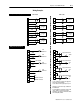
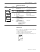
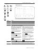
Interpret Status Indicators
Indicators
If indicator
➀
Is ON Is OFF
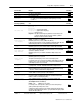
ACTIVE
the CFM module is successfully receiving
power and operational
a. Check FAULT LED if on, follow the
steps listed under if FAULT is ON.
b. Check power supply.
INPUTS
(F0 F3)
F0 - flashes with pulses at Channel 1
F1 - flashes with pulses at Channel 2
F2 - flashes with pulses at Channel 3
F3 - flashes with pulses at Channel 4
a signal is not present at the designated
input terminal
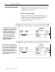
S0
S1 S2 S3
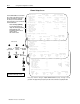
ACTIVE
INPUTS/OUTPUTS
STATUS
F0 F1 F2 F3
G0 G1 G2 G3
O0 O1 O2 O3
STATUS S1
S2
S3
S4
BTW invalid (BTW word 1, bits 0815) 0 0
BTW is occurring
BTR is occurring
frequency > 10.0kHz (overrange) on
any channel
BTW is valid
BTW is not occurring
BTR is not occurring
all frequencies within operating range
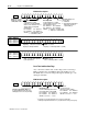
S0
S1 S2 S3
S4 S5 S6 S7
FAULT
FAULT
1. Turn off power to the I/O chassis
backplane and wiring arm.
2. Reseat the CFM module in the
I/O chassis.
3. Restore power to the I/O chassis
backplane and wiring arm.
Important: If the fault LED remains on,
there may be an internal problem.
Contact your local
AllenBradley representative for
additional assistance.
normal operation
➀
All other LED'
s are OFF in normal operation.
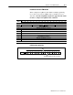
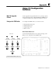
Additional Feature
When you replace your existing QRD module with the CFM module,
you can set input channel jumpers for:
• 500mV ac sensitivity for improved noise immunity
• frequencies > 70Hz (flowmeter filter jumpers)
For additional information on setting the input channel jumpers, see:
Install the
CFM Module
2