
Manual

Replace Your QRD Module D–9
Publication
17716.5.99 - December 1995
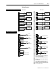
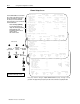
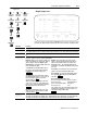
Read Data From the CFM Module
When configured for QRD module emulation, BTR programming
moves nine words from the CFM module to the PLC processor’s
data table. The following BTR assignments apply when the CFM
module is configured for QRD module emulation.
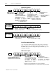
BTR
Bit
BTR
Word
15
14 13 12 11 10 09 08 07 06 05 04 03 02 01 00
Block
ID & Channel Status
1 Header Overflow
Status
Overrange Alarm
Error Code
Input
Channel Data
2
Frequency on Channel 1 (010,000)
3
Total on Channel 1 (032,767)
4
Frequency on Channel 2 (010,000)
5
Total on Channel 2 (032,767)
6
Frequency on Channel 3 (010,000)
7
Total on Channel 3 (032,767)
8
Frequency on Channel 4 (010,000)
9
Total on Channel 4 (032,767)
*ALL numeric values are in binary*
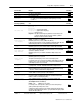
BTR Word Description Key
15 14 13 12 11 10 09 08 07 06 05 04 03 02 01 00
Bits
Description of what these bits are used for.
word #