
Manual

Replace Your QRD Module D–7
Publication
17716.5.99 - December 1995
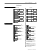
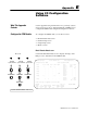
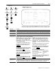
Wiring Examples
11
12
(-)
(+)
turbine
flowmeter
1
15
16
(-)
(+)
turbine
flowmeter
2
23
24
(-)
(+)
turbine
flowmeter
3
27
28
(-)
(+)
turbine
flowmeter
4
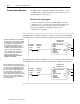
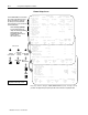
wiring for magnetic pickups or flowmeters
3
4
5
shield
(+)
(-)
turbine
flowmeter
1
6
7
8
shield
(+)
(-)
turbine
flowmeter
2
9
10
11
shield
(+)
(-)
turbine
flowmeter
3
12
13
14
shield
(+)
(-)
turbine
flowmeter
4
QRD module CFM module
3
4
shield
6
7
8
shield
9
10
11
12
13
17
shield
TTL
channel 1
TTL
channel 2
logic ground
TTL
channel 3
shield
TTL
channel 4
9
11
12
TTL
➀
F0
logic
ground channel 0
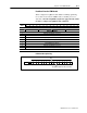
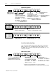
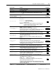
wiring for active TTL drivers
19
20
13
15
16
TTL
F1
logic
ground channel 1
21
23
24
logic ground channel 2
25
27
28
TTL
F3
logic ground channel 3
➀
To use a channel in TTL, jumper the appropriate
TTL pin to the appropriate RET.
To use Channel 1 in TTL, jumper pin 9 to pin 11.
Signal types can be mixed in any combination on
the CFM module.
➁
For new installations, terminate the shields at the
chassis. While not recommended, existing
installations can continue to terminate the shields
at the return (RET) terminal.
TTL
channel 3 & 4 level
channel 1 & 2 level
TTL
F2
➁
➁
➁
➁