
Manual

Replace Your QRD ModuleD–6
Publication
17716.5.99 - December 1995
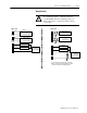
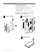
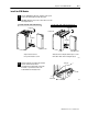
Connect your I/O devices to the 40-terminal field wiring arm
(cat. no. 1771-WN) shipped with the CFM module. Use the wiring
examples on page D–7 for additional assistance on connecting
your devices.
F0 Input
F1 Input
F2 Input
F3 Input
actual wiring runs in this direction
Even Numbered T
erminals 240
Odd Numbered T
erminals 139
NEW wiring arm (1771WN)OLD wiring arm (1771WG)
not
used
not used
Channel 1 +
Channel 1 -
shield
Channel 2 +
Channel 2 -
shield
Channel 3+
Channel 3 -
shield
Channel 4 +
Channel 4 -
shield
not used
not used
TTL
not used
Channel 3, 4 level
Channel 1, 2 level
not used
18322
F0 (TTL)
➀
F0 RET
F1 (TTL)
F1 RET
F2 (TTL)
F2 RET
F3 (TTL)
F3 RET
2
4
6
8
10
12
14
16
18
20
22
24
26
28
30
32
34
36
38
40
1
3
5
7
9
11
13
15
17
19
21
23
25
27
29
31
33
35
37
39
1
2
3
4
5
6
7
8
9
10
11
12
13
14
15
16
17
18
19
20
21
➀
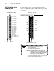
To use a channel in TTL, jumper the appropriate TTL pin to the appropriate
RET. To use Channel 1 in TTL, jumper pin 9 to pin 11.
The sensor cable must be shielded. The shield:
• must extend the length of the cable, but be connected
only at the 1771 I/O chassis
• must extend up to the point of termination
Important: The shield should extend to the termination point,
exposing just enough cable to adequately terminate the
inner conductors. Use heat shrink or another suitable
insulation where the wire exits the cable jacket.
Make Connections to the
New Wiring Arm