
Manual
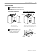

Replace Your QRC Module C–9
Publication
17716.5.99 - December 1995
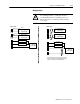
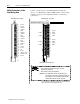
Read Data From the CFM Module
When configured for QRC module emulation, BTR programming
moves three words from the CFM module to the PLC processor’s
data table. The following BTR assignments apply when the CFM
module is configured for QRC module emulation.
BTR
Bit
BTR
Word
15
14 13 12 11 10 09 08 07 06 05 04 03 02 01 00
Block
ID
1 Header
Input Channel Rate
2
Rate of Ratemeter A
3
Rate of Ratemeter B
*ALL numeric values are in binary*
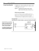
BTR Word Descriptions
15 14 13 12 11 10 09 08 07 06 05 04 03 02 01 00
Header
will
be 7001 Hex or 28,673 binary. Identifies the
module as a CFM (QRC) module.
word 1
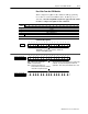
15 14 13 12 11 10 09 08 07 06 05 04 03 02 01 00
Rate indicates the calculated rate.
RANGE: 015,800Hz binary
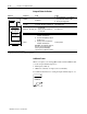
15 14 13 12 11 10 09 08 07 06 05 04 03 02 01 00
word 2 (ratemeter A)
00000000 00010111
The rates in words 2 & 3 are updated every 13.5ms20ms
maximum. The greater the frequency, the faster the
update time. The accuracy of the returned rate is ±1Hz.
Rates: 0169Hz are reported as zero
17015,800Hz are reported as calculated
> 15,800Hz are reported as 15,800
word 3 (ratemeter B)