
Manual

Schematics B–3
Publication 17716.5.99 - December 1995
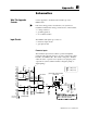
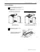
Gate Inputs
Gate inputs are used for running prover and store count values.
Each gate is an electrically isolated circuit with a physical and
electrical isolation of 1500V ac. There is one gate associated with
each flowmeter input circuit (G0 corresponds to F0).
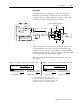
JPR 6 JPR 7
R4 R2
Q1
D3
D2
R79
R77
Voltage
Jumpers
D1
Input
RET
GO
G1
G2
G3
U12
+5V
C52
R87
G0
G1
G2
G3
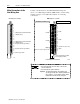
physical and electrical isolation
1500V ac rms
gate jumpers:
JPR6 = ON for 1240V dc
JPR7 = ON for 512V dc
E11 E11 E11
R1
C51
C55
7
29
31
GO
G1
G2
G3
8
30
32
5
6
external device
470Ω 470Ω
330Ω
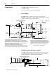
To turn on a gate circuit, you must source current through the input
resistors sufficient to turn on the opto-isolator in the circuit. If no
connection is made to the pair of gate terminals, no current will flow
through the photodiode of the opto-isolator and that gate will be OFF
(the corresponding input status indicator is OFF).
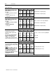
The input current magnitude can be determined by the state of the
gate jumper:
CASE A gate jumper set for 512V dc operation (JPR 7 is ON)
gate input current = (gate input voltage - 2V
➀
)
330Ω
➁
gate input current = (gate input voltage - 2V
➀
)
1270Ω
➁
If gate input voltage = 40V dc
gate input current = (40V - 2V)
1270
Ω
gate input current = 30mA
➁
If gate input voltage = 5V dc
gate input current = (12V - 2V)
1270
Ω
gate input current = 8mA
➁
Examples
If gate input voltage = 12V dc
gate input current = (12V - 2V)
330Ω
gate input current = 30mA
➁
If gate input voltage = 5V dc
gate input current = (5V - 2V)
330Ω
gate input current = 9mA
➁
Examples
CASE B gate jumper is set for 1240V dc operation (JPR 6 is ON)
➀
There is approximately a 2V drop across (Q1 + the photodiode).
➁
The operating range of the input is 510mA and Q1 functions as an overcurrent
protection circuit. If an open collector device with pullup is used, the value of
the pullup must be added to the
Ω
value shown in the denominator
.