
Manual
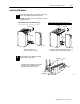

SchematicsB–2
Publication
17716.5.99 - December 1995
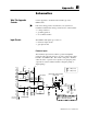
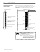
Signal characteristics
50mV threshold
Input
50mV
threshold
Turbine flowmeter or magnetic pickup
F0 F1 F2 F3
T
ur
bi
ne
fl
owmeter or magnet
i
c p
i
c
k
up
(50mV142V ac rms)
The signal:
12
16 24 28 + turbine flowmeter or magnetic pickup
The
signal:
• should be approximately sinusoidal
• must be ac
11
15 23 27 - turbine flowmeter or magnetic pickup
must
be
ac
• must be > 100mV and < 400V
F0 RET
F1 RET F2 RET F3 RET
us be 00 a d 00
peaktopeak
Input Return
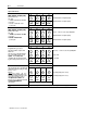
500mV threshold
Input
T
u
r
b
in
e
fl
o
wm
e
t
e
r
o
r m
ag
n
e
ti
c
p
i
c
k
up
F0 F1 F2 F3
T
ur
bi
ne
fl
owme
t
er or magne
ti
c p
i
c
k
up
(500mV142V ac rms)
The signal:
h ld b i t l i id l
10
14
22
26
500mV connect to each corresponding RET
• should be approximately sinusoidal
• must be ac
• must be > 1V and < 400V
12
16
24
28
+ turbine flowmeter or magnetic pickup
• must be > 1V and < 400V
peaktopeak
11 15 23 27 - turbine flowmeter or magnetic pickup
F0 RET F1 RET F2 RET F3 RET
Input Return
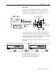
1.3V threshold (TTL)
Input
()
Compatible with open collector.
F0
F1 F2 F3
Compatible
with
open
collector
.
The signal should be dc pulses with
width > 4us.
9
13 21 25
1.3V (TTL) connect to each corresponding RET
The TTL mode is compatible with TTL,
4000 series CMOS, and most 024V
systems The TTL mode in not
12 16 24 28
+ logic circuit
systems.
Th
e
TTL
mo
d
e
i
n not
compatible with any signal format with
dc pulses riding on a fixed dc level > 1.3V.
11
15 23 27 - logic GND
pg
F0 RET F1 RET F2 RET F3 RET
Input Return
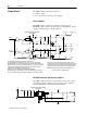
12" V threshold (+24V RET)
Input
This specialized mode is compatible with
signal format with pulses riding on a fixed
F0 F1 F2 F3
signal
format
with
pulses
riding
on
a
fixed
dc level > +1.3V.
Example
Bently Nevada Proximity Pickup Series
1212 16 24 28
+ proximity pickup (active sensor)
B
ent
l
y
N
eva
d
a
P
rox
i
m
i
ty
Pi
c
k
up
S
er
i
es
3300 (5mm and 8mm) where the active"
sensor signals are with a 5V offset.
The signal resides between 5
18V
18
18
20 20
- proximity pickup (active sensor)
Th
e s
i
gna
l
res
id
es
b
e
t
ween
5
18V
,
therefore, it passes through the threshold
of
12
"
V as referenced to the
S0 RET S1 RET S2 RET S3 RET
o
f
12"V as re
f
erenced to the
+24V dc RET.
Input Return
#
wiring
arm terminal number
Signal threshold (500mV or 1.3V) is selected by jumpering the appropriate level to the appropriate RET.