
Manual

Appendix
B
Publication
17716.5.99 - December 1995
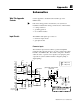
Schematics
Use this appendix to understand the internal logic of the
CFM module.
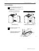
Follow the wiring practices described in your system-level
installation manual when wiring your I/O devices. This includes:
• routing conductors
• grounding practices
• use of shielded cables
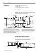
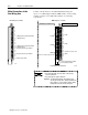
The CFM module input logic consists of:
• flowmeter input circuits
• gate input circuits
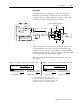
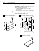
Flowmeter Inputs
The flowmeter input circuit combines operational amplifier
principles with solid state devices to provide constant logic pulses
internal to the CFM module. The circuit is designed to interface
with both active or passive sensor inputs by accepting any pulse
output device (such as turbine flowmeter, magnetic pickup or
digital pickup).
RET
+12V +12V
R119
R123
R98
RV1
R7
C64
C72
D9
R112 R109 R116
C73
D11
U23
Σ
∞
R115
D7
R108
U26
U22
U17
+5V
V
REF
50mV
C62 R120
C81
E6
E6
E6
C9
JPR20
JPR21
70Hz
filter
physical and electrical isolation
500V ac rms
500mV
level
TTL
level
(1.3V)
Input
F0
F1
F2
F3
1
2
1
2
1
2
1
2
1
2
1
2
1
2
1
2
11
15
23
27
F0
F1
F2
F3
28
24
16
12
F3
F2
F1
F0
25
21
13
9
F3
F2
F1
F0
25
21
13
9
F3
F2
F1
F0
26
22
14
10
F3
F2
F1
F0
flowmeter jumpers:
JPR20 = ON for highspeed operation
JPR21 = ON for filter operation
= COM (F0 & F1)
= COM (F2 & F3)
18
20
- proximity pickup
-12V (F0 &F1)
-12V (F2 & F3)
8.25kΩ 215kΩ 1kΩ
4.7kΩ
26.1kΩ
What This Appendix
Contains
"
Input Circuits