
Manual


Chapter
6
Publication
17716.5.99 - December 1995
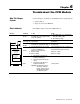
Troubleshoot the CFM Module
Use this chapter to troubleshoot the CFM module by interpreting the:
• status indicators
• diagnostic word in the BTR file
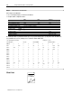
The CFM module provides these LED indicators:
Indicators If indicator Is ON Is OFF
ACTIVE
the CFM module is successfully receiving
power and operational
a. Check FAULT LED if on, follow the steps
listed under if FAULT is ON.
b. Check the power supply.
INPUTS
(F0F3 & G0G3)
a signal is present at the designated
input terminal
a signal is not present at the designated
input terminal
OUTPUTS
(O0O3)
the module has commanded an output on the output is off
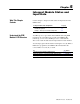
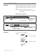
ACTIVE
INPUTS/OUTPUTS
STATUS
F0 F1 F2 F3
G0 G1 G2 G3
O0 O1 O2 O3
S1
STATUS
S2
S3
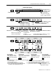
Powerup Bit (BTR word 1, bit 00) is ON
(=1) BTW hasn't occurred since
powerup, or invalid BTW, or
PLC processor in Program mode
BTW is occurring
BTR is occurring
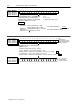
Powerup Bit (BTR word 1, bit 00) is OFF (=0)
valid BTW has occurred since powerup or since
last switched from Program to Run mode
BTW is not occurring
BTR is not occurring
S0 S1 S2 S3
S4 S5 S6 S7
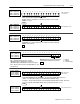
FAULT
STATUS
FAULT
1. Turn off power to the I/O chassis
backplane and wiring arm.
2. Reseat the CFM module in the I/O
chassis.
3. Restore power to the I/O chassis
backplane and wiring arm.
Important: If the fault LED remains on,
there may be an internal
problem. Contact your local
AllenBradley representative
for additional assistance.
normal operation
What This Chapter
Contains
Status Indicators