
Manual


5–3Interpret Module Status and Input Data
Publication
17716.5.99 - December 1995
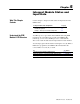
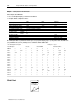
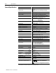
BTR Word Descriptions
15 14 13 12 11 10 09 08 07 06 05 04 03 02 01 00
Powerup Bit indicates if
a valid BTW has occurred
since powerup or since
last switched from
Program to Run mode.
Header must be 0010.
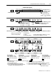
15 14 13 12 11 10 09 08 07 06 05 04 03 02 01 00
Error Words & Diagnostics displays
invalid BTW word # (060 BCD).
99 = invalid BTW length.
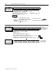
15 14 13 12 11 10 09 08 07 06 05 04 03 02 01 00
Mode Indication for Channel 2
Mode Indication for Channel 0
Mode Indication for Channel 3
Mode Indication for Channel 1
Output Status reflects current
operating state of outputs.
b12 = Output 0 b13 = Output 1
b14 = Output 2 b15 = Output 3
VALUES:
0 = OFF
1 = ON
word 3
word 2
word 1
0010
0 = unused channel
1 = Totalizer 3 = Highresolution Frequency (channels 0 & 1 or 2 & 3)
2 = Nonresettable Totalizer 4 = Direction Sensor (channels 0 & 1 or 2 & 3)
Indicates mode of operation that
channel is currently running in.
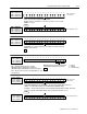
15 14 13 12 11 10 09 08 07 06 05 04 03 02 01 00
Channel 0Channel 1
Prover Status indicates the current state of prover (value of bits in hex).
0 = prover not selected 4 = prover is returning on reverse leg (bidirectional only)
1 = prover not running, but active 5 = prover is done with run (BTR word 13/14 contains prover count value)
2 = prover running past the 1st switch in forward leg 6 = prover not active & new store count A
3 = prover is done with forward leg and returning at this time 7 = prover not active & new store count B
intermediate value returned (bidirectional only)
Overrange
Alarm
Overflow
Status
Prover
Status
15 14 13 12 11 10 09 08 07 06 05 04 03 02 01 00
Channel 2Channel 3
Overrange Alarm
on if the frequency is > than
100kHz (frequencies > 100kHz
may not be accurately returned).
Acceleration Alarm
on if |acceleration value| is >
Acceleration Alarm Value
(BTW word 9, 19, 29, 39).
Overspeed Alarm
on if frequency is >
Highest Allowable Frequency
(BTW word 8, 18, 28, 38).
Overflow Status
toggles between 0101 every time a
rollover occurs. This bit is reset by
BTW word 1 (bits 0407).
Acceleration
Alarm
Overspeed
Alarm
Overrange
Alarm
Overflow
Status
Prover
Status
Acceleration
Alarm
Overspeed
Alarm
word 4
word 5
allall
all
T,
NR
T
T
, NR
T
if prover not active,
these bits toggle 6767 every
high transition of the gate
VALUES: 1= no or invalid BTW
0 = yes