
Manual


5–2 Interpret Module Status and Input Data
Publication
17716.5.99 - December 1995
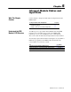
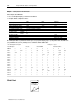
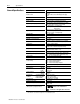
BTR Word Assignments
Word(s)
Bit
Word(s)
15
14 13 12 11 10 09 08 07 06 05 04 03 02 01 00
Block
ID & Resets
1 Header
Powerup
bit
Output Status & Diagnostics
2
Output Status
Error
Words & Diagnostics
Mode
Indication
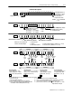
3 Channel
3
Channel 2
Channel 1
Channel 0
Channel 1 Status
Channel 0 Status
4
Prover
Status
Overrange
Alarm
Overflow
Status
Overspeed
Alarm
Acceleration
Alarm
Prover Status
Overrange
Alarm
Overflow
Status
Overspeed
Alarm
Acceleration
Alarm
Channel 3 Status
Channel 2 Status
5
Prover
Status
Overrange
Alarm
Overflow
Status
Overspeed
Alarm
Acceleration
Alarm
Prover Status
Overrange
Alarm
Overflow
Status
Overspeed
Alarm
Acceleration
Alarm
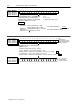
Input
Channel Data
Channel 0 (words 614) Channel 1 (words 1523) Channel 2 (words 2432) Channel 3 (words 3341)
6,
15, 24, 33
Percent of Full Scale (Rate % of High RPM value)
7, 16, 25, 34 Frequency (0120 ) MSD
8, 17, 26, 35
Frequency (0999) LSD
9, 18, 27, 36
T
otal MSD (0999)
10, 19, 28, 37
T
otal LSD (09,999)
1
1, 20, 29, 38
Acceleration (rate of change of frequency)
12, 21, 30, 39
Direction
13, 22, 31, 40
Prover T
otal Count V
alue or Store Count V
alue MSD (0999)
14, 23, 32, 41
Prover T
otal Count V
alue or Store Count Value LSD (09,999)
not used
* Numeric values are in binary except for
Diagnostics
(word 2, bits 0007)
*
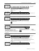
BTR Word Description Key
15 14 13 12 11 10 09 08 07 06 05 04 03 02 01 00
Bits
Mode(s) that use these bits.
Description of what these bits are used for.
not used
word #
Mode
abbreviations:
Totalizer = T
Nonresettable T
otalizer = NR
T
Highresolution Frequency = HR
Direction Sensor = DS