
Manual


Chapter
5
Publication
17716.5.99 - December 1995
Interpret Module Status and
Input Data
Use this chapter to interpret module status and input data from the
CFM module.
To interpret module status and input data See page
Understand The CFM Module's BTR Structure . . . . . . . . . . . .
5-1
BTR Word Assignments . . . . . . . . . . . . . . . . . . . . . . . . . 5-2
Example PLC5 processor Status and Input Data . . . . .
5-6
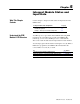
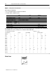
Your PLC processor gets data from the CFM module using BTR
instructions in your ladder logic program. The CFM module
transfers up to 41 words to the PLC processor’s data table file.
The words contain module status and input data from each channel.
You should program a block transfer read length of zero (0). When a
BTR of 0 is programmed, the CFM module will determine the
correct number of words (41) to return.
For See page(s)
a general overview of the BTW configuration block 5-2
detailed descriptions of each word in the BTW configuration block 5-3 through 5-5
an example of a data table print out 5-6
What This Chapter
Contains
Understand the CFM
Module's BTR Structure