
Manual

4–14 Configure the CFM Module
Publication
17716.5.99 - December 1995
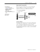
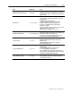
Direction Sensor Mode
Use this mode to measure shaft direction. In this mode, the
CFM module calculates:
• rate of input (0-100,000Hz)
• acceleration value
• direction of shaft
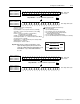
BTR
status and input data
1771CFM
F0
G0
F1
G1
not used
not used
BTW
configuration
PLC processor
uses channels 0&1 or 2&3
F0 & F1 used in TTL
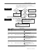
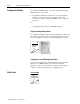
Frequency
Sampling
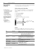
In this mode, frequency samples are taken every revolution by
measuring A and B:
A
= the time between F0 input channel pulses (determines shaft frequency)
B
= the time between F0 and F1 input channel pulses (determines shaft direction)
If Direction is
B < 1/2 A
clockwise
B > 1/2 A
counterclockwise
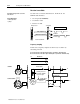
low true signal
B
A
sensor F1
shaft
low true signal
proximity sensors at
F0 and F1 should be
60 to 120° apart
notch
F0
F1
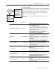
F1
shaft
B
F0
A
clockwise
counterclockwise
F1
shaft
B
A
F0
Both sensors cannot be low at
the same time.
Use this mode if you want to determine
shaft direction.
Typical Applications:
• turbine generators
• pumps