
Manual

4–3Configure the CFM Module
Publication
17716.5.99 - December 1995
BTW Word Descriptions
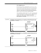
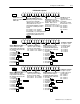
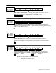
Output 0 Trigger selects what
channel characteristic output 0
is triggered ON or OFF by placing
the shown hex values in these bits:
0 = Force OFF
1 = Frequency
2 = % of Fullscale Frequency
3 = Acceleration
4 = Total Value
5 = Direction
6 = Overflow
7 = Prover Running
8 = Prover Range
F = Force ON
Tie Output 1 to Channel ties
output 1 to operate according to
the state of a specific channel.
b08 = Counter 0 b10 = Counter 2
b09 = Counter 1 b11 = Counter 3
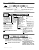
15 14 13 12 11 10 09 08 07 06 05 04 03 02 01 00
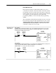
Total Reset resets the
total count for the
appropriate counter on a 0
to 1 transition.
Only occurs on a change
in bit state from a 0 to a 1.
b00 = Counter 0
b01 = Counter 1
b02 = Counter 2
b03 = Counter 3
Overflow Reset resets the
overflow status of the module for
the appropriate counter on a 0 to 1
transition. Only occurs on a
change in bit state from a 0 to a 1.
b04 = Counter 0 b06 = Counter 2
b05 = Counter 1 b07 = Counter 3
Prover Run Initialize initializes the
channel for prover inputs on the Gate.
Also resets Store Count Value
(BTR words 13 & 14). Only occurs on a
change in bit state from a 0 to a 1.
This bit should remain ON (= 1) until the
prover is done or until the prover run is
aborted.
b08 = Counter 0 b10 = Counter 2
b09 = Counter 1 b11 = Counter 3
If this bit is OFF (= 0), a low to high transition
of the Gate will store the current count in
Store Count Value (BTR words 13 & 14).
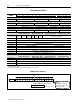
Header must be 0010.
Identifies the module as a
CFM module.
T
T, NRT
T, NRT
15 14 13 12 11 10 09 08 07 06 05 04 03 02 01 00
Tie Output 0 to Channel
ties output 0 to operate
according to the state
of a specific channel.
b00 = Counter 0
b01 = Counter 1
b02 = Counter 2
b03 = Counter 3
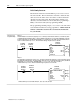
Output 1 Trigger selects what
channel characteristic output 1
is triggered ON or OFF by placing
the shown hex values in these bits:
0 = Force OFF
1 = Frequency
2 = % of Fullscale Frequency
3 = Acceleration
4 = Total Value
5 = Direction
6 = Overflow
7 = Prover Running
8 = Prover Range
F = Force ON
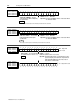
Tie Output 3 to Channel ties
output 3 to operate according to
the state of a specific channel.
b08 = Counter 0 b10 = Counter 2
b09 = Counter 1 b11 = Counter 3
15 14 13 12 11 10 09 08 07 06 05 04 03 02 01 00
Tie Output 2 to Channel
ties output 2 to operate
according to the state of
a specific channel.
b00 = Counter 0
b01 = Counter 1
b02 = Counter 2
b03 = Counter 3
word 3
word 2
word 1
0010
all
T,
NR
T
DS
T
, NR
T
all
Output 3 Trigger selects what
channel characteristic output 3
is triggered ON or OFF by placing
the shown hex values in these bits:
0 = Force OFF
1 = Frequency
2 = % of Fullscale Frequency
3 = Acceleration
4 = Total Value
5 = Direction
6 = Overflow
7 = Prover Running
8 = Prover Range
F = Force ON
Output 2 Trigger selects what
channel characteristic output 2
is triggered ON or OFF by placing
the shown hex values in these bits:
0 = Force OFF
1 = Frequency
2 = % of Fullscale Frequency
3 = Acceleration
4 = Total Value
5 = Direction
6 = Overflow
7 = Prover Running
8 = Prover Range
F = Force ON
all
T,
NR
T
, HR
all
T
, NR
T
DS
T
, NR
T
all
all
T
, NR
T
, HR
all
T
, NR
T
DS
T
, NR
T
all
all
T
, NR
T
, HR
all
T
, NR
T
DS
T
, NR
T
all
all
T
, NR
T
, HR