
Manual
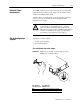
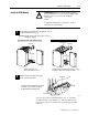

2–10 Install the CFM Module
Publication
17716.5.99 - December 1995
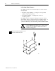
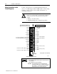
5-12V dc
OR
12-40V dc
S
1
2
4
6
8
10
12
G0 RET
G0
1
3
5
7
9
11
external device
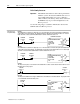
Standard Prover/Store Count (G0)
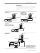
Standard Output (O0)
External
Power Supply #1
540V dc @ 2A
28
30
32
34
36
38
40
27
29
31
33
35
37
39
Output 1
+
-
LOAD 1
+
-
LOAD 1
+
-
LOAD 0
1771WN
Customer V DC #1 (5 to 40V)
Output 0
1771WN
Customer V DC #1 RET
(Outputs 0 & 1 RET)
➀
For new installations, terminate the shields at
the chassis. While not recommended,
existing installations can continue to terminate
the shields at the return (RET) terminal.
➀
➀
➀
➀
+
-
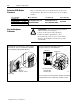
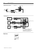
Edit Your
Ladder Logic
Program
3
What's Next