
Manual
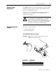
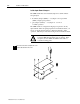
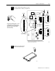
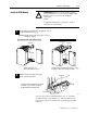

2–9Install the CFM Module
Publication
17716.5.99 - December 1995
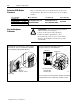
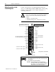
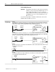
Wiring Examples
These wiring diagrams represent wiring for a flowmeter input (F0),
a gate input (G0) and an output (O0). See the wiring arm diagram
on page2–8 for the terminals used in wiring F1-F3, G1-G3
and O1-O3.
1
3
5
7
9
11
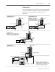
Standard TTL or Open Collector
1.3V threshold (F0)
Important: To use a channel in TTL, jumper
the appropriate TTL pin to the appropriate RET
.
To use Channel 0 in TTL, jumper pin 9 to pin 11.
2
4
6
8
10
12
1
3
5
7
9
11
+
-
Input
Device
2
4
6
8
10
12
1771WN
2
4
6
8
10
12
1
3
5
7
9
11
F0 (500mV)
F0 Input
F0 (TTL)
not used
F0 RET
not used F0 (500mV)
F0 Input
+
-
Input
Device
F0 (TTL)
not used
F0 RET
+
-
Input
Device
Standard Magnetic Pickup
500mV threshold (F0)
Important: T
o use a channel for
500mV sensor
, jumper the 500mV
pin to the appropriate RET
.
For
Channel 0, jumper pin 10 to pin 1
1.
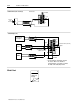
Standard Magnetic Pickup
50mV threshold (F0)
1771WN
not
used F0 (500mV)
F0 Input
F0 (TTL)
F0 RET
1771WN
not used
F0 (500mV)
F0 (TTL)
not used
F0 RET not used
+24V DC source #1 @ 12mA to power a proximity transducer
Standard Proximity
using CFM Module Source (F0)
2
4
6
8
10
12
14
16
18
20
+24V
DC source #1 @ 12mA RET (- proximity pickup)
1
3
5
7
9
11
13
15
17
19
+
-
Input
Device
+
-
1771WN
F0 Input
➀
For new installations, terminate the shields at
the chassis. While not recommended,
existing installations can continue to terminate
the shields at the return (RET) terminal.
➀
➀
➀ ➀
➀