
Manual

2–6 Install the CFM Module
Publication
17716.5.99 - December 1995
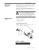
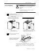
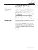
Place your module in any slot of the I/O chassis except for the
extreme left slot. This slot is reserved for processors or adapter
modules.
Use of data table 2slot addressing 1slot addressing 1/2slot addressing
Input Image Bits 8
Place the CFM module in any
Place the CFM module in any
Output Image Bits 8
Place the CFM module in any
module group with any 8
bit or
Place the CFM module in any
module group with any 8
bit
no restrictions
Read Block Words 41 max
mo
d
u
l
e group w
ith
any
8
bit
or
block transfer module.
mo
d
u
l
e group w
ith
any
8
bit
,
16bit or block transfer module.
no restr
i
ct
i
ons
Write Block Words
60 max
block
transfer
module
.
16
bit
or
block
transfer
module
.
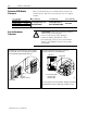
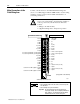
!
ATTENTION: Observe the following precautions
when inserting or removing keys:
• insert or remove keys with your fingers
• make sure that key placement is correct
Incorrect keying or the use of a tool can result in
damage to the backplane connector and possible
system faults.
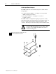
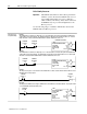
Position the keying bands in the backplane connectors to
correspond to the key slots on the CFM module.
keying bands
19808
Place the keying bands:
between 2 and 4
between 6 and 8
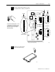
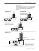
The CFM module is slotted in two places on the rear edge of
the circuit board. These slots are intended to mate with the
plastic keying bands supplied with the I/O chassis.
You can change the position of these bands if subsequent system design
and rewiring makes insertion of a different type of module necessary.
I/O chassis
CFM module
I/O chassis
backplane connector
Determine CFM Module
Placement
Key the Backplane
Connector