
Manual

1–5Overview of the CFM Module
Publication
17716.5.99 - December 1995
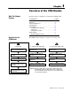
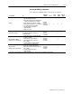
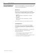
Selecting the Mode(s) of Operation
You configure the CFM module for these modes of operation:
Use this mode To
Indicators/
Alarms
Prover
Total
reset
Scaler
values
Rollover
value
Totalizer
• accurately measure counts using a flowmeter
or positive displacement meter
• trigger outputs directly from the CFM module
trigger on total, frequency, acceleration
• monitor flow total, rate, and rate of change
independent of your PLC processor scan times
• store counts based on external input
• scale the frequency and count to
engineering units
• interface to a prover
overrange
overflow
overspeed
acceleration
√ √ √ √
Nonresettable Totalizer
operate in the Totalizer mode with the count
reset function disabled to prevent loss of
accumulated value
overrange
overflow
overspeed
acceleration
√ √ √
Highresolution Frequency
➀
(channels 0&1 or channels 2&3)
• monitor the frequency of an input with high
accuracy (e.g. shaft)
• monitor the rate of speed change
• operate outputs based on speed or
rate of change
• scale the frequency to engineering units
overspeed
overrange
acceleration
√
Direction Sensor
➀
(channels 0&1 or channels 2&3)
• monitor the direction of shaft rotation
• monitor rate of change and frequency
• trigger outputs based on direction, frequency,
rate of change
• scale the frequency and count to
engineering units
overspeed
acceleration
overrange
√
➀
This mode uses two channels for one input (your input device is connected to F0 or F2, while F1 or F3 is unused).