Allen Bradley Configurable Flowmeter Module (1771 CFM/B) User Manual
Important User Information Because of the variety of uses for the products described in this publication, those responsible for the application and use of this control equipment must satisfy themselves that all necessary steps have been taken to assure that each application and use meets all performance and safety requirements, including any applicable laws, regulations, codes and standards.
Table of Contents Important User Information . . . . . . . . . . . . . . . . . . . . . . . . -1 Using This Manual . . . . . . . . . . . . . . . . . . . . . . . . . . . . . . . P-1 What's In This Manual . . . . . . . . . . . . . . . . . . . . . . . . . . . . . . . . New/Updated Information . . . . . . . . . . . . . . . . . . . . . . . . . . . . . . Abbreviations . . . . . . . . . . . . . . . . . . . . . . . . . . . . . . . . . . . . . . Related Documentation . . . . . . . . . . . . . . . . . . . . . . .
ii Table of Contents Edit Your Ladder Logic Program . . . . . . . . . . . . . . . . . . . . 3-1 What This Chapter Contains . . . . . . . . . . . . . . . . . . . . . . . . . . . . Enter Block Transfer Instructions . . . . . . . . . . . . . . . . . . . . . . . . . PLC 2 Family Processor . . . . . . . . . . . . . . . . . . . . . . . . . . . . . PLC 3 Family Processor . . . . . . . . . . . . . . . . . . . . . . . . . . . . . PLC 5 Family Processor . . . . . . . . . . . . . . . . . . . . . . . . . . . . .
Table of Contents iii Specifications . . . . . . . . . . . . . . . . . . . . . . . . . . . . . . . . . . A-1 What This Appendix Contains . . . . . . . . . . . . . . . . . . . . . . . . . . . Frequency Accuracy . . . . . . . . . . . . . . . . . . . . . . . . . . . . . . . . . General Specifications . . . . . . . . . . . . . . . . . . . . . . . . . . . . . . . . A-1 A-1 A-2 Schematics . . . . . . . . . . . . . . . . . . . . . . . . . . . . . . . . . . . . B-1 What This Appendix Contains . . . . . . .
iv Table of Contents Edit Your Ladder Logic Program . . . . . . . . . . . . . . . . . . . . . . . Read Data From the CFM Module . . . . . . . . . . . . . . . . . . . . . . BTR Word Description Key . . . . . . . . . . . . . . . . . . . . . . . . . BTR Word Descriptions . . . . . . . . . . . . . . . . . . . . . . . . . . . Reset Total and Overflow Flags . . . . . . . . . . . . . . . . . . . . . . . . BTW Word Description . . . . . . . . . . . . . . . . . . . . . . . . . . . . Interpret Status Indicators . .
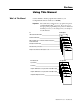
Preface Using This Manual What's In This Manual Use this manual to install, program and troubleshoot your Configurable Flowmeter module (1771-CFM/B). Important: We assume that you know how to program and operate an Allen-Bradley PLC processor. If you do not, see the appropriate programming and operations manual for the PLC processor you are using, before you attempt to use this manual.
P–2 Using This Manual New/Updated Information ÎÎÎ Î ÎÎ The1771-CFM/B is marked with the logo, indicating that this version complies with the European Union Directives. Technical additions and corrections are marked with change bars.
Using This Manual Related Documentation Document Configurable Flowmeter Module Product Data PLC 2 Programming Software Documentation Set (D6200 L06) PLC 2 Programming Software Programming Manual PLC 3 Programming Software Documentation Set (D6200 L07) PLC 3 Programming Software Programming Manual PLC 5 Programming Software Documentation Set (6200 N8.001) PLC 5 Programming Software I/O Configuration Manual PLC 5/250 Programming Software Documentation Set (6200 N8.
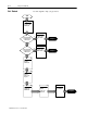
P–4 Using This Manual Get Started Use this diagram to help you get started. Start 1 Overview of the CFM Module A Using CFM module as replacement for QRC module? Y Replace Your QRC Module Complete N B Using CFM module as replacement for QRD module? Y Replace Your QRD Module Complete N 2 Install the CFM Module 3 Edit Your Ladder Logic Program 4 Configure the CFM Module Publication 1771 6.5.
Chapter 1 Overview of the CFM Module What This Chapter Contains How You Use the CFM Module Read this chapter to familiarize yourself with the CFM module. For information on See page How You Use the CFM Module . . . . . . . . . . . . . . . . . . . . . . . What's Next . . . . . . . . . . . . . . . . . . . . . . . . . . . . . . . . . . . . What the CFM Module Does . . . . . . . . . . . . . . . . . . . . . . . . Typical Applications . . . . . . . . . . . . . . . . . . . . . . . . . . . . . . .
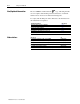
1–2 Overview of the CFM Module What's Next The rest of this chapter contains information on CFM module operation. Using the CFM module as a replacement for a QRC module? C Y N Using the CFM module as replacement for a QRD module? D Y N 1 What the CFM Module Does The CFM module performs high-speed totalizing and/or rate calculation operations for various industrial applications.
Overview of the CFM Module Typical Applications 1–3 You can use the CFM module in the power management, automotive, food and beverage, and oil and gas industries for various flow and/or turbine metering applications.
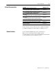
1–4 Overview of the CFM Module Input Capabilities The CFM module accepts input for up to four channels (mode dependent).
Overview of the CFM Module 1–5 Selecting the Mode(s) of Operation You configure the CFM module for these modes of operation: Prover Totalizer • accurately measure counts using a flowmeter or positive displacement meter • trigger outputs directly from the CFM module trigger on total, frequency, acceleration • monitor flow total, rate, and rate of change independent of your PLC processor scan times • store counts based on external input • scale the frequency and count to engineering units • interface to a
1–6 Overview of the CFM Module Using a Prover A prover is used for the calibration of liquid meters in custody transfer applications. This calibration is done by comparing a metered throughput to a known volume in the prover. The number of pulses accumulated (Prover Total Count Value), while the spheroid moves between two detectors, is then compared to the predetermined volume of the prover section to ascertain the meter factor.
Overview of the CFM Module Output Capabilities 1–7 The CFM module has four assignable outputs. These outputs are designed for applications that require fast response.
1–8 Overview of the CFM Module Implementing Application Features You can use the CFM module to implement programmable application features that are usually initiated by your PLC processor. This frees the PLC processor to do other tasks and helps increase the overall throughput of your PLC system.
Chapter 2 Install the CFM Module What This Chapter Contains Follow the instructions in this chapter to install the CFM module. To install the CFM module Understand Compliance to European Union Directive . . . . . . Calculate Power Requirements . . . . . . . . . . . . . . . . . . . . . . Set the Configuration Jumpers . . . . . . . . . . . . . . . . . . . . . . . Check the Module Operation Jumper . . . . . . . . . . . . . . . . Set the Input Channel Jumpers . . . . . . . . . . . . . . . . . . . .
2–2 Install the CFM Module Understand Compliance to European Union Directive If this product has the CE mark it is approved for installation within the European Union and EEA regions. It has been designed and tested to meet the following directives.
Install the CFM Module Calculate Power Requirements 2–3 Your CFM module receives its power through the 1771 I/O chassis backplane from the chassis power supply. The maximum current drawn by the CFM module is 1.0A. Add this value to the requirements of all other modules in the I/O chassis to prevent overloading the chassis backplane and/or backplane power supply.
2–4 Install the CFM Module Set the Input Channel Jumpers The CFM module has user-selectable jumpers for each flowmeter and gate input: • flowmeter jumpers (F0-F3) — set jumper for low-pass filter (70Hz) or high-speed operation • gate jumpers (G0-G3) — set jumper for +5-12V or +12-40V operation The CFM module is configured for high-speed operation. If any input channel will be accepting input from a mechanical switch, you need to set the flowmeter jumper for that input channel to filter operation.
Install the CFM Module 2 2–5 Reposition the flowmeter and gate jumpers associated with each input channel according to your requirements. 5-12V FILTER➀ 12-40V G0 HIGH SPEED F1 G1 F0 jumpers➁ can be The flowmeter and gate set independent of each other (you can select the filter action for each flowmeter input and a voltage for each and gate input independently). gate jumpers F3 G2 F2 flowmeter jumpers G3 13 ➀ In the filter position, the module will not read frequencies above 70Hz.
2–6 Install the CFM Module Determine CFM Module Placement Use of data table Input Image Bits Output Image Bits Read Block Words Write Block Words 8 8 41 max 60 max Key the Backplane Connector Place your module in any slot of the I/O chassis except for the extreme left slot. This slot is reserved for processors or adapter modules. 2 slot addressing 1 slot addressing 1/2 slot addressing Place the CFM module in any module group with any 8 bit or block transfer module.
Install the CFM Module Install the CFM Module 2–7 ATTENTION: Remove power from the 1771 I/O chassis backplane before you install the CFM module. Failure to remove power from the backplane could cause: ! • injury • equipment damage due to unexpected operation • degradation of performance 1 Place the module in the card guides on the top and bottom of the slot that guide the CFM module into position. Important: Apply firm even pressure on the module to seat it into its backplane connector.
2–8 Install the CFM Module Make Connections to the Field Wiring Arm Connect your I/O devices to the 40-terminal field wiring arm (cat. no. 1771-WN) shipped with the CFM module. Use the wiring examples on pages 2–9 and 2–10 for additional assistance on connecting your devices. ! ATTENTION: Remove power to all I/O devices before you connect them to the wiring arm.
Install the CFM Module 2–9 Wiring Examples These wiring diagrams represent wiring for a flowmeter input (F0), a gate input (G0) and an output (O0). See the wiring arm diagram on page2–8 for the terminals used in wiring F1-F3, G1-G3 and O1-O3. Standard Magnetic Pickup 50mV threshold (F0) Standard Magnetic Pickup 500mV threshold (F0) Important: To use a channel for 500mV sensor, jumper the 500mV pin to the appropriate RET. For Channel 0, jumper pin 10 to pin 11.
2–10 Install the CFM Module Standard Prover/Store Count (G0) 5-12V dc OR 12-40V dc external device 1771 WN 2 4 6 8 10 12 G0 RET + S 1 1 3 G0 5 7 9 11 ➀ Standard Output (O0) External Power Supply #1 5 40V dc @ 2A + - 28 ➀ Output 0 LOAD 0 + - 32 34 36 ➀ Customer V DC #1 RET (Outputs 0 & 1 RET) LOAD 1 30 38 40 27 29 31 33 35 Customer V DC #1 (5 to 40V) Output 1 37 39 + - 1771 WN ➀ ➀ For new installations, terminate the shields at the chassis.
Chapter 3 Edit Your Ladder Logic Program What This Chapter Contains To initiate communication between the CFM module and your PLC processor, you must enter block transfer instructions into your ladder logic program. Use this chapter to enter the necessary block transfer instructions into your ladder logic program. To edit your ladder logic you Enter Block Transfer Instructions . . . . . . . . . . . . . . . . . . . . . PLC 2 Family Processors . . . . . . . . . . . . . . . . . . . . . . . .
3–2 Edit Your Ladder Logic Program PLC 2 Family Processor Important: The CFM module functions with reduced performance in PLC-2 systems. Because the CFM module does not support BCD and the PLC-2 processor is limited to values of 4095 (12 bit binary), many values returned in the BTR file may not provide meaningful data to the PLC-2 processor. Use the following rungs to establish communication between the CFM module and a PLC-2 processor.
Edit Your Ladder Logic Program 3–3 PLC 3 Family Processor Block transfer instructions with the PLC-3 processor use a control file and a data file. The block transfer control file contains the data table section for module location, the address of the block transfer data file and other related data. The block transfer data file stores data that you want transferred to the module (when programming a BTW) or from the module (when programming a BTR).
3–4 Edit Your Ladder Logic Program PLC 5 Family Processor Block transfer instructions with the PLC-5 processor use a control file and a data file. The block transfer control file contains the data table section for module location, the address of the block transfer data file and other related data. The block transfer data file stores data that you want transferred to the module (when programming a BTW) or from the module (when programming a BTR).
Edit Your Ladder Logic Program 3–5 PLC 5/250 Processor Block transfer instructions with the PLC-5/250 processor use a control file and a data file. The block transfer control file contains the data table section for module location, the address of the block transfer data file and other related data. The block transfer data file stores data that you want transferred to the module (when programming a BTW) or from the module (when programming a BTR).
3–6 Edit Your Ladder Logic Program What's Next 4 Configure the CFM Module Publication 1771 6.5.
Chapter 4 Configure the CFM Module What This Chapter Contains Use this chapter to configure the CFM module. To configure the CFM module Understand the CFM Module's BTW Structure . . . . . . . . . . . . BTW Configuration Block . . . . . . . . . . . . . . . . . . . . . . . . 4-2 Select the Mode(s) of Operation . . . . . . . . . . . . . . . . . . . . . . 4-8 Configure the CFM Module . . . . . . . . . . . . . . . . . . . . . . . . . 4-16 Using I/O Configuration Software . . . . . . . . . . . . . . . .
4–2 Configure the CFM Module BTW Configuration Block Bit➁ Word(s)➀ 15 14 13 12 11 10 09 08 07 06 05 04 03 02 01 00 Block ID & Resets 1 Header Prover Run Initialize Overflow Reset Total Reset Output 0 Trigger Tie Output 0 to Channel Output 2 Trigger Tie Output 2 to Channel Channel 1 Channel 0 Output 1 and Output 0 Trigger & Select 2 Output 1 Trigger Tie Output 1 to Channel Output 3 and Output 2 Trigger & Select 3 Output 3 Trigger Tie Output 3 to Channel Input Channel Oper
Configure the CFM Module 4–3 BTW Word Descriptions word 1 15 14 13 12 0 0 1 0 Header must be 0010. Identifies the module as a CFM module. 15 11 10 09 08 07 06 05 04 03 02 01 00 Prover Run Initialize initializes the Overflow Reset resets the channel for prover inputs on the Gate. overflow status of the module for Also resets Store Count Value the appropriate counter on a 0 to 1 (BTR words 13 & 14). Only occurs on a transition. Only occurs on a change in bit state from a 0 to a 1.
4–4 Configure the CFM Module 15 14 13 12 11 10 09 08 07 06 05 04 03 02 01 00 word 4 Operating Mode for Channel 0 Operating Mode for Channel 2 Operating Mode for Channel 1 Select a mode of operation on a per 0 = unused channel channel basis by placing the shown 1 = Totalizer 3 = High resolution Frequency (channels 0 & 1 or 2 & 3)➀ hex values in the proper bits: 2 = Nonresettable Totalizer 4 = Direction Sensor (channels 0 & 1 or 2 & 3)➀➁ Operating Mode for Channel 3 ➀ These modes are selec
Configure the CFM Module word 7 word 17 word 27 word 37 (channel 0) (channel 1) (channel 2) (channel 3) 15 14 13 12 11 10 09 08 07 06 05 04 03 02 01 4–5 00 Number of Pulses to Terminate Sampling applied when Sampling Termination (bit 13 of word 5, 15, 25 or 35) is set. Causes the sampling to cease when the specified number of input pulses are received or the Minimum Frequency Sampling Time is exceeded, which ever occurs first.
4–6 word 11 word 21 word 31 word 41 Configure the CFM Module (channel 0) (channel 1) (channel 2) (channel 3) 15 14 13 12 11 10 09 08 07 06 05 04 03 02 01 00 RANGE: 0 32,767 DEFAULT: 1 Important: The Total Scaler Multiplier must be ≤ Total Scaler Divisor. See Total Scaler Divisor. Total Scaler➀ Multiplier the total value returned in the BTR is multiplied by the specified value. T, NRT ➀ When scaling is used, all outputs are still controlled by the actual value not the scaled value.
Configure the CFM Module word 45 word 49 word 53 word 57 (channel 0) (channel 1) (channel 2) (channel 3) 15 14 13 12 11 10 Output ON Value word 46 word 50 word 54 word 58 (channel 0) (channel 1) (channel 2) (channel 3) 09 08 07 06 15 14 13 12 11 10 09 15 14 13 12 11 10 09 Output OFF Value word 48 word 52 word 56 word 60 (channel 0) (channel 1) (channel 2) (channel 3) 03 02 01 00 MSD ranges from 0 999 x 10,000 all LSD ranges from 0 9,999 08 07 06 08 07 05 04 03
4–8 Configure the CFM Module Select the Mode(s) of Operation You select the mode(s) of operation and configure each input channel to accept input signals from your input device(s).
Configure the CFM Module 4–9 Frequency Sampling Bandwidth Limit (word 5, bit 14) set (ON)? N and no pulses are received after the sampling time expires, the frequency is calculated up to 2s after the initial pulse and will measure frequencies as low as 1Hz. Y and no pulses are received within one more sample time, the frequency will then be calculated. The minimum frequency is then 1/Minimum Frequency Sampling Time and the maximum time period is 2 x Minimum Frequency Sampling Time.
4–10 Configure the CFM Module Storing Count Value In the Totalizer and Nonresettable Totalizer modes, the CFM module stores the current count based on these values: Value BTW word # Use to initialize an input channel for prover inputs on the gate or to store current count value (if prover not used). If OFF (=0) CFM module stores the current count every time there is a low to high transition at the appropriate gate input terminal.
Configure the CFM Module 4–11 High resolution Frequency Mode Use this mode if you: • need accurate frequency value (see page A-1 for frequency accuracy) • need fastest possible sample update time across large frequency range • want to calculate acceleration • need to measure frequency in 10ths of Hz (0.1Hz) This mode measures incoming pulses over a user-specified time interval (4-1000ms) or over a user-specified number of input signal pulses.
4–12 Configure the CFM Module You can specify these values: Value Use to specify the minimum time the CFM module will spend collecting 6, 16, 26, 36 pulses to determine a frequency. The sample begins on the Minimum Frequency Sampling Time➀ leading edge of a pulse. terminate the sampling on either a time base or a set number of Sampling Termination 5, 15, 25, 35 (bit 13) pulses, depending on which occurs first.
Configure the CFM Module 4–13 Use these diagrams to understand how you use Sampling Termination and Bandwidth Limit to exert even more control over the CFM module’s frequency sampling. Sampling Termination (for input channel 0) Sampling Termination (word 5, bit 13) set (ON)? Y Minimum Frequency Sampling Time (word 6) expired? The CFM module calculates frequency on the next pulse to occur after time expires.1 Y CFM module calculates frequency immediately after the specified number of pulses occur.
4–14 Configure the CFM Module Direction Sensor Mode Use this mode if you want to determine shaft direction. Use this mode to measure shaft direction.
Configure the CFM Module Value BTW word # Minimum Frequency Sampling Time 6, 16, 26, 36 4–15 Use to determine the minimum frequency and maximum sample time. All sample times are based on the time between F0 or F2 pulses. If Bandwidth Limit is OFF (= 0), Minimum Frequency Sampling Time is not used. control the maximum time the CFM module spends calculating a frequency and the minimum frequency that can be read by the CFM module.
4–16 Configure the CFM Module Configure the Module To configure the CFM module, you set the appropriate bits in the BTW instruction. You do this: • through I/O Configuration software if you are using a PLC-5 family processor (see PLC-5 Programming Software I/O Configuration Manual, publication 6200-6.4.
Chapter 5 Interpret Module Status and Input Data What This Chapter Contains Use this chapter to interpret module status and input data from the CFM module. To interpret module status and input data Understand The CFM Module's BTR Structure . . . . . . . . . . . . BTR Word Assignments . . . . . . . . . . . . . . . . . . . . . . . . . Example PLC 5 processor Status and Input Data . . . . .
5–2 Interpret Module Status and Input Data BTR Word Assignments Bit Word(s) 15 14 13 12 11 10 09 08 07 06 05 04 03 02 01 ÉÉÉÉÉÉ ÉÉÉÉÉÉÉÉÉÉÉÉÉÉÉÉÉÉÉÉÉÉ ÉÉÉÉÉÉ ÉÉÉÉÉÉÉÉÉÉÉÉÉÉÉÉÉÉÉÉÉÉ ÉÉÉÉÉÉÉÉÉÉ ÉÉÉÉÉÉÉÉÉÉ ÉÉ ÉÉ ÉÉ ÉÉ ÉÉ ÉÉ ÉÉ ÉÉ ÉÉ ÉÉ 00 Block ID & Resets 1 Power up bit Header Output Status & Diagnostics 2 Output Status Error Words & Diagnostics Mode Indication 3 Channel 3 Channel 2 Channel 1 Channel 0 Channel 1 Status 4 Prover Status Overrange Alarm Channel 0 Status Ov
Interpret Module Status and Input Data 5–3 BTR Word Descriptions word 1 ÉÉÉÉÉÉÉÉÉÉÉÉÉÉ ÉÉÉÉÉÉÉÉÉÉÉÉÉÉ 15 14 13 12 0 0 1 0 Header must be 0010. 11 10 09 08 07 06 05 04 03 02 01 00 Power up Bit indicates if a valid BTW has occurred since power up or since last switched from Program to Run mode. VALUES: 1= no or invalid BTW 0 = yes word 2 15 14 13 ÉÉÉÉÉÉ ÉÉÉÉÉÉ 12 11 10 09 08 07 06 Output Status reflects current operating state of outputs.
5–4 word 65 word 15 word 24 25 word 33 35 Interpret Module Status and Input Data (Channel 0) (Channel 1) (Channel 2) (Channel 3) 15 14 13 12 11 10 09 08 07 06 Percent of Full Scale (Rate % of High RPM value) the calculated frequency scaled by the Highest Allowable Frequency (BTW 8, 18, 28, 38) and then expressed as a number from 0 to 32,767.
Interpret Module Status and Input Data word 9 word 18 word 27 word 36 (channel 0) (channel 1) (channel 2) (channel 3) 15 14 13 12 11 10 09 08 07 06 05 04 03 02 01 00 5–5 MSD ranges from 0 999 x 10,000 Total the total counts registered by the input channel.
5–6 Example Interpret Module Status and Input Data reading data from the CFM module In this example, the CFM module: • has a constant input frequency of 729Hz fed to all channels • has input channels configured as follows: CH 0 Totalizer 50ms 25000 3500 10 (every 10 frequency samples) 360000 6 36 Operating Mode Minimum Frequency Sampling Time Highest Allowable Frequency Acceleration Alarm Value Acceleration Calculation Time Rollover Value Frequency Scaler Multiplier Divisor Frequency in 10ths Bandwidt
Chapter 6 Troubleshoot the CFM Module What This Chapter Contains Use this chapter to troubleshoot the CFM module by interpreting the: Status Indicators The CFM module provides these LED indicators: Indicators ACTIVE INPUTS/OUTPUTS F0 F1 F2 F3 G0 G1 G2 G3 O0 O1 O2 O3 • status indicators • diagnostic word in the BTR file If indicator Is ON ACTIVE the CFM module is successfully receiving power and operational Is OFF a. Check FAULT LED if on, follow the steps listed under if FAULT is ON. b.
6–2 Troubleshoot the CFM Module Diagnostics The CFM module returns diagnostics to the PLC processor in words one and two of the BTR file. These diagnostics give you the number of the word in the BTW configuration block that has caused an error to occur. Important: In the event that there are multiple incorrect BTW words, the CFM module only returns the first incorrect word.
Appendix A Specifications What This Appendix Contains This appendix contains the frequency accuracy and general specifications of the CFM module. Frequency Accuracy The following table lists typical application configurations and their associated frequency accuracy for the CFM module when used: • to emulate a 1771-QRC or 1771-QRD module • as a CFM module Important: The accuracy in all configurations will vary with input frequency, mode of operation and frequency sample time.
A–2 Specifications General Specifications Number of Input Channels 4 Module Location 1771 A1B, A2B, A3B, A3B1, A4B (series A and B) I/O chassis 1771 AM1, AM2 I/O chassis with integral power supply, adapter Maximum Count Value 0-9,999,999 (programmable) BTW Processing Time (worst case) 5.5ms Module Scan Time 1.
B Appendix Schematics What This Appendix Contains Use this appendix to understand the internal logic of the CFM module. " Follow the wiring practices described in your system-level installation manual when wiring your I/O devices.
B–2 Schematics Signal characteristics 50mV threshold Turbine flowmeter or magnetic pickup (50mV 142V ac rms) The signal: • should be approximately sinusoidal • must be ac • must us be > 100mV 00 and a d < 400V 00 peak to peak 500mV threshold Turbine flowmeter or magnetic pickup (500mV 142V ac rms) The signal: • should h ld be b approximately i t l sinusoidal i id l • must be ac • must be > 1V and < 400V peak to peak F0 F1 12 11 F0 RET Input F2 F3 16 24 28 + turbine flowmeter or magnetic pickup
Schematics B–3 Gate Inputs Gate inputs are used for running prover and store count values. Each gate is an electrically isolated circuit with a physical and electrical isolation of 1500V ac. There is one gate associated with each flowmeter input circuit (G0 corresponds to F0).
B–4 Schematics Output Circuits The CFM module output logic consists of: • discrete outputs • dc to dc converters (24V dc power supplies) Discrete Outputs The CFM module’s outputs are comprised of isolated power MOSFETs. These devices operate in current sourcing mode, and are capable of delivering up to 1A (@ 5-40V dc).
Appendix C Replace Your QRC Module What This Appendix Contains Use this appendix to install the CFM module as a replacement for the QRC module. To replace your QRC module you Check Power Requirements . . . . . . . . . . . . . . . . . . . . . . . . . Remove Your QRC Module . . . . . . . . . . . . . . . . . . . . . . . . . Set the Configuration Jumpers . . . . . . . . . . . . . . . . . . . . . . . Set the Module Operation Jumper . . . . . . . . . . . . . . . . . . Check the Input Channel Jumpers . . . . .
C–2 Replace Your QRC Module Remove Your QRC Module ATTENTION: Remove power from the 1771 I/O chassis backplane and wiring arm before you remove your QRC module. Failure to remove power from the backplane could cause: ! • injury • equipment damage due to unexpected operation • degradation of performance 1 Detach and remove wiring arm (1771 WG) from the horizontal bar at the bottom of the I/O chassis. wiring arm 1771 WG remove horizontal bar 2 17643 Remove the QRC module from the I/O chassis.
Replace Your QRC Module Set the Configuration Jumpers C–3 You check and/or set these jumpers: • module operation jumper • input channel jumpers Set the Module Operation Jumper To use the CFM module as a replacement for a QRC module, set the operation jumper in the QRC position (default setting = CFM position). CFM module CFM QRC QRD 19807 Publication 1771 6.5.
C–4 Replace Your QRC Module Check the Input Channel Jumpers The CFM (QRC) module has user-selectable jumpers for each input channel. These jumpers consist of one each: • flowmeter jumpers (F0–F3) - set for low-pass filter or high-speed operation • gate jumpers (G0–G3) — set for +5-12V or +12-40V operation " 1 The CFM (QRC) module is configured for high-speed operation. Before installing your CFM (QRC) module, make sure the input channel jumpers are in their default positions.
Replace Your QRC Module C–5 Install the CFM Module 1 Place the CFM (QRC) module in the card guides on the top and bottom of the slot that guide the module into position. Important: Apply firm even pressure on the module to seat it into its backplane connector.
C–6 Replace Your QRC Module Make Connections to the New Wiring Arm Connect your I/O devices to the 40-terminal field wiring arm (cat. no. 1771-WN) shipped with the CFM module. Use the wiring example on page C–7 for additional assistance on connecting your devices.
Replace Your QRC Module C–7 Wiring Example ! QRC module CFM module shield 7 ATTENTION: Pins15 & 18 (on the QRC module) are switching negative (–) while pins 34 & 35 (on the CFM module) are switching positive (+). Please take this into consideration when rewiring your system.
C–8 Replace Your QRC Module Resume Normal Operation The CFM module, configured for QRC module emulation, operates as a QRC module. Use the following section for reference on how the CFM (QRC) module operates. Important: The CFM module has 50mV sensitivity. This is different than the QRC module, which had 20 to 300mV sensitivity, depending on the hardware level.
Replace Your QRC Module C–9 Read Data From the CFM Module When configured for QRC module emulation, BTR programming moves three words from the CFM module to the PLC processor’s data table. The following BTR assignments apply when the CFM module is configured for QRC module emulation.
C–10 Replace Your QRC Module Interpret Status Indicators Indicators If indicator➀ Is ON ACTIVE the CFM module is receiving power and operational INPUTS (F0 & F2) ACTIVE INPUTS/OUTPUTS F0 F1 F2 F3 G0 G1 G2 G3 O0 O1 O2 O3 STATUS S0 S S S1 S S2 S S3 S4 S5 S6 S7 F0 - flashes with pulses at Channel A F2 - flashes with pulses at Channel B OUTPUTS➁ (O0 & O1) STATUS Is OFF S3 FAULT O0 - indicates Channel A frequency is ≥ 15,800Hz O1 - indicates Channel B frequency is ≥ 15,800Hz BTR is occurring 1.
Appendix D Replace Your QRD Module What This Appendix Contains Use this appendix to install the CFM module as a replacement for the QRD module. To replace your QRD module you Check Power Requirements . . . . . . . . . . . . . . . . . . . . . . . . . . . . . Remove Your QRD Module . . . . . . . . . . . . . . . . . . . . . . . . . . . . . Set the Configuration Jumpers . . . . . . . . . . . . . . . . . . . . . . . . . . . Set the Module Operation Jumper . . . . . . . . . . . . . . . . . . . . . .
D–2 Replace Your QRD Module Check Power Requirements ATTENTION: The maximum current drawn by the CFM(QRD) module is 1.0A. This current (1.0A) is 0.5A greater than the maximum current drawn by your QRD module (0.5A). Consider the power usage of all modules in the I/O chassis to prevent overloading either the chassis backplane or power supply. ! Remove Your QRD Module ATTENTION: Remove power from the 1771 I/O chassis backplane and wiring arm before you remove your QRD module.
Replace Your QRD Module Set the Configuration Jumpers D–3 You check and/or set these jumpers: • module operation jumper • input channel jumpers Set the Module Operation Jumper To use the CFM module as a replacement for a QRD module, set the operation jumper in the QRD position (default setting = CFM position). CFM module CFM QRC QRD 19807 Publication 1771 6.5.
D–4 Replace Your QRD Module Check the Input Channel Jumpers The CFM (QRD) module has user-selectable jumpers for each input channel. These jumpers consist of one each: • flowmeter jumpers (F0–F3) - set for low-pass filter or high-speed operation • gate jumpers (G0–G3) — set for +5-12V or +12-40V operation The CFM (QRD) module is configured for high-speed operation. Before installing your CFM (QRD) module, make sure the input channel jumpers are in their default positions.
Replace Your QRD Module D–5 Install the CFM Module 1 Place the CFM (QRD) module in the card guides on the top and bottom of the slot that guide the module into position. Important: Apply firm even pressure on the module to seat it into its backplane connector.
D–6 Replace Your QRD Module Make Connections to the New Wiring Arm Connect your I/O devices to the 40-terminal field wiring arm (cat. no. 1771-WN) shipped with the CFM module. Use the wiring examples on page D–7 for additional assistance on connecting your devices.
Replace Your QRD Module D–7 Wiring Examples wiring for magnetic pickups or flowmeters QRD module 3 4 5 7 10 12 (-) turbine flowmeter (+) 1 (+) turbine flowmeter (-) 2 15 (-) 16 turbine flowmeter (+) 2 (+) turbine flowmeter (-) 3 23 (-) 24 turbine flowmeter (+) 3 (+) turbine flowmeter (-) 4 27 (-) shield 12 13 14 11 shield 9 11 (+) turbine flowmeter (-) 1 shield 6 8 CFM module turbine flowmeter (+) 4 28 shield wiring for active TTL drivers TTL channel 1 3 4 shield shield
D–8 Replace Your QRD Module Resume Normal Operation The CFM module, configured for QRD module emulation, operates as a QRD module. Use the following section for reference on how the CFM (QRD) module operates. Edit Your Ladder Logic Program To initiate communication between the CFM (QRD) module and your PLC processor, you must enter block transfer instructions into your ladder logic program. The following program example illustrates the minimum programming required for this communication to take place.
Replace Your QRD Module D–9 Read Data From the CFM Module When configured for QRD module emulation, BTR programming moves nine words from the CFM module to the PLC processor’s data table. The following BTR assignments apply when the CFM module is configured for QRD module emulation.
D–10 Replace Your QRD Module BTR Word Descriptions word 1 15 14 13 0 0 0 . 1 Header must be 0001 Identifies the module as a CFM (QRD) module. word 25 word 415 word 625 word 835 (channel 1) 0) (channel 2) 1) (channel 3) 2) (channel 4) 3) 12 11 10 09 08 Overflow Status on if rollover has occurred (counter has exceeded maximum value of 32,767 and rolled over to 0). This can only be reset by BTW Overflow Reset.
Replace Your QRD Module D–11 Interpret Status Indicators Indicators If indicator➀ Is ON ACTIVE the CFM module is successfully receiving power and operational INPUTS (F0 F3) ACTIVE INPUTS/OUTPUTS STATUS S1 F0 F1 F2 F3 G0 G1 G2 G3 O0 O1 O2 O3 STATUS S0 S1 S2 S3 S4 S5 S6 S7 FAULT F0 - flashes with pulses at Channel 1 F1 - flashes with pulses at Channel 2 F2 - flashes with pulses at Channel 3 F3 - flashes with pulses at Channel 4 BTW invalid (BTW word 1, bits 08 15) 0 0 Is OFF a.
Appendix E Using I/O Configuration Software What This Appendix Contains Use this appendix along with the PLC-5 Programming Software, I/O Configuration Software manual (publication 6200-6.4.12) to configure the CFM module using I/O Configuration software.
E–2 Using I/O Configuration Software Channel Setup Screen 1771–CFM Series A Shows current values for each channel (these values reflect the data received the last time a BTR was completed). The PLC processor must be in Run mode if you want to receive current data from the CFM module. Shows current programming for each channel and lets you change the channel programming. Fields inapplicable in the programmed channel mode are shown as dashes and cannot be edited.
Using I/O Configuration Software Current values channel mode frequency total counts acceleration Current programming E–3 Displays the current channel mode as returned in the BTR data file by the module the current scaled frequency the scaled total counts if acceleration alarm value 0 0, value = the acceleration (change in scaled frequency per second) = 0, value = 0 In mode(s) You press (F9) Toggle to select a mode of operation for the input channel: In mode(s) all all T, NRT all ❯ not used ❯ tota
E–4 Using I/O Configuration Software Current programming scalers for total (multiply/divide) rollover value tied to outputs reset total reset overflow start prover prover type, uni or bidirectional Mode abbreviations: Totalizer = T You enter a multiplier and divisor here, separated by a (/) to have the module report total counts in units meaningful to your application (the multiplier must be ≤ the divisor) RANGE: 0 32,767 DEFAULT: 1/1 (no scaling) For example, if 15 counts represent 2 gallons, you
Using I/O Configuration Software Choose one: a or Ladder Editor Main Menu b F7 Counter Setup or Monitor or BT Data Ladder Editor Main Menu General Utility Cursor to BT instruction Output Setup Screen c or Output Setup F4 Edit I/O Ovrview F10 F9 1771–CFM Series A 0–0–0 output number current status Output Setup tied to channel forced or triggered by Rack–Group–Module: ON when >= OFF when >= 0 off 0 rate/frequency 1,000 25,000 1 off 2 total 1,000 3,500,000 2 on 0 rate/fre
E–6 Using I/O Configuration Software Monitor Screen Choose one: a Ladder Editor Main Menu b c Counter Setup I/O Module or System Overview or or Output Setup or BT Data Cursor to Monitor BT instruction F3 Edit Monitor F2 F5 or Data Monitor Output Setup F8 Use the monitor screen to check and verify the configuration data. The values on this screen reflect the data received the last time a BTR was completed. The processor must be in Run mode if you want to receive current data from the module.
Allen Bradley Publication Problem Report If you find a problem with our documentation, please complete and return this form.
E–2 Configurable Flowmeter Module User Manual Pub. Name Cat. No. 1771 CFM/B Check Problem(s) Type: Pub. No. 1771 6.5.99 Pub. Date November 1995 Part No.
E–3 Publication 1771 6.5.
E–4 PLEASE FASTEN HERE (DO NOT STAPLE) PLEASE FOLD HERE NO POSTAGE NECESSARY IF MAILED IN THE UNITED STATES BUSINESS REPLY MAIL FIRST-CLASS MAIL PERMIT NO. 18235 CLEVELAND OH POSTAGE WILL BE PAID BY THE ADDRESSEE 1 ALLEN BRADLEY DR Publication 1771 6.5.
Index Symbols **Empty**, -1 Numbers 1771 QRC module, C-1 A abbreviations, P-2 acceleration, 1-8 applications features, 1-8 modes of operation, 1-5, 4-11 prover, 1-6 typical, 1-3 B block transfer BTR, 1-2 BTW, 1-2 block transfer programming, 3-1 PLC 2 family processor, 3-2 PLC 3 family processor, 3-3 PLC 5 family processor, 3-4 PLC 5/250 processor, 3-5 BTR, 1-2 diagnostics, 6-2 structure, 5-1 word assignments, 5-1, 5-2 word descriptions, 5-3, 5-4, 5-5 BTW, 1-2 configuration block, 4-2 word descriptions,
I–2 Index D dc to dc converters, circuit diagram, B-4 Direction Sensor mode, 1-5, 1-7, 4-14 frequency sampling, 4-14, 4-15 E EMC Directive. See European Union Directive European Union Directive, CFM module compliance, 2-2 F F0 F3. See flowmeter input flowmeter input, 1-4 circuit diagram, B-1 operation jumper, 2-4, 2-5 signal characteristics, B-2 wiring examples, 2-9 G G0 G3. See gate input G0 G3.
Index P PLC 2 family processor, block transfer programming, 3-2 PLC 3 family processor, block transfer programming, 3-3 PLC 5 family processor, block transfer programming, 3-4 PLC 5/250 processor, block transfer programming, 3-5 power, requirements, 2-3 power requirements, 2-3 I–3 specifications, CFM module, A-2 frequency accuracy, A-1 store count, 1-6 gate input wiring, 2-10 T Totalizer and Nonresettable Totalizer modes counting, 4-8 frequency sampling, 4-9 storing count values, 4-10 programming, PLC-
Allen Bradley, a Rockwell Automation Business, has been helping its customers improve productivity and quality for more than 90 years. We design, manufacture and support a broad range of automation products worldwide. They include logic processors, power and motion control devices, operator interfaces, sensors and a variety of software. Rockwell is one of the world's leading technology companies. Worldwide representation.