
User Manual Owner's manual

Settings for 1771–AS and 1771–ASB Series A, B, C and D Remote I/O Adapters B–5
Publication 1771ĆUM001A-US-P - February 2000
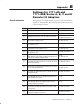
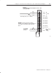
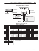
Figure B.5
Module Switch Assembly Settings for 1771-ASB series C
and D Adapters for PLCĆ2 Family Processors
1 2 3 4 56 78
O
N
O
F
F
O
N
O
F
F
1234
First I/O group number
(Table B.B)
I/O rack number
(Table B.B)
Address Switch Assembly
(S1)
Switch Assembly
(S2)
SD Ć always OFF
SD2 Ć without complementary I/O Ć always OFF
SD2 Ć with complementary I/O Ć
ON Ć Primary chassis
OFF Ć Complementary chassis
Pressed in at top
Closed (ON)
Pressed in at bottom
Open (OFF)
Maximum I/O
chassis distance
SD Ć always ON
SD2 Ć without complementary I/O
Ć always ON
SD2 Ć with complementary I/O Ć
ON Ć Primary chassis
OFF Ć Complementary chassis
Always ON
56
Link Response Ć ON for series B emulation
Scan Ć on for all but last 4 slots
off for all slots
OFF for unrestricted
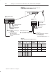
Switch Position
12
57.6K Baud Ć 10,000ft
115.2K Baud Ć 5,000ft
Not Used
Not Used
10798ĆI
ATTENTION: Link response switch must
be ON when using the following scanner
modules:
1772ĆSD2
ON OFF
OFF OFF
ON ON
ONOFF
Off
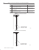
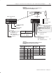
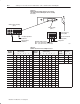
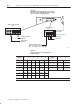
Table B.B
I/O Rack Number and First I/O Group Switch Selections for
the Address Switch Assembly S1 (PLCĆ2 Family
Processors)
I/O Rack
Number
Switch Selections
456
First I/O Group
Number
Switch Selections
78
1 On On On 0 On On
2 On On Off 2 On Off
3 On Off On 4 Off On
4 On Off Off 6 Off Off
5 Off On On
6 Off On Off
7 Off Off On