
User Manual Owner's manual


3–23Addressing Modes for Your Remote I/O
&%"! #&#'
Follow these guidelines when you select 1/2-slot addressing:
• Place input modules opposite output modules; place output
modules opposite input modules.
• You can use 8, 16 and 32-point I/O modules.
• Output modules placed opposite output modules reflect the same
bits in the output image table.
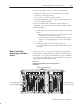
You can use block-transfer modules in a complementary I/O
configuration with 1/2-slot addressing. Use block-transfer modules
with these guidelines:
• When using double-slot block-transfer modules in the primary
chassis:
– The left-most slot of the two corresponding I/O slots in the
complementary chassis must be empty.
– You can place any single-slot I/O module in the right slot
of the two corresponding I/O slots of the complementary
chassis
• When using single-slot block-transfer modules, the
corresponding I/O slot in the complementary chassis must be
left empty.
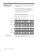
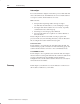
You can have a mix of 1-slot and 2-slot addressing in individual
chassis assigned one I/O rack number (with up to eight I/O groups).
For example: you can select 2-slot addressing for a 1771-A2B I/O
chassis and 1-slot addressing for a 1771-A1B chassis to make up one
assigned I/O rack number (Figure 3.20).
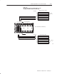
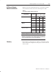
Figure 3.20
Mixing Addressing Methods in Chassis Assigned One I/O
Rack Number
( $$$
&$! ($"% #$$!
( $$$
&$! ($"% #$$!
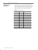
! $$! & #
1 2 3 4-5 6-70
Mixing 1 and 2ĆSlot
Addressing in Individual
Chassis