
User Manual Owner's manual


3–22 Addressing Modes for Your Remote I/O
3"+)#!2).- %"03!05
Some processors support a complementary I/O configuration. Refer
to the user’s manual for your processor to see if it supports this type
of configuration.
You configure complementary I/O by duplicating an I/O rack
number of one I/O chassis (primary) in another I/O chassis
(complementary), I/O group for I/O group. The I/O modules in the
complementary chassis perform the opposite function of the
corresponding modules in the primary chassis.
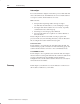
Module Placement with 1/2Ćslot Addressing
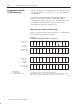
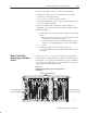
Figure 3.19 shows possible module placement for a complementary
I/O configuration with 1/2-slot addressing.
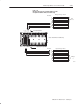
Figure 3.19
Complementary I/O Configuration with 1/2Ćslot Addressing
.3"+%1+.2
4!,/+%
4!,/+%
0),!05 1+.2
(!11)1
0.3/
3,"%0
.,/+%,%-2!05
1+.2 (!11)1
0),!05 1+.2
(!11)1
0.3/
3,"%0
.,/+%,%-2!05
1+.2 (!11)1
-/32.$3+%
32/32 .$3+%
+.#* 20!-1&%0 .$3+%
32/32 ,.$3+%1 31% 2(% 1!,% .32/32 ),!'% 2!"+% ")21
!- "% )-/32 .0 .32/32 ,.$3+% .0 /.)-2 1)-'+%1+.2 "+.#* 20!- &%0 ,.$3+%
312 "% %,/25 )& #.00%1/.-$)-' /0),!05 1+.2 )1 "+.#* 20!-1&%0 ,.$3+%
1
Complementary I/O with
1/2ĆSlot Addressing