
User Manual Owner's manual

3–19Addressing Modes for Your Remote I/O
)! ( $# &)&*
Definition: The processor addresses one-half of an I/O module slot as
one I/O group.
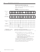
Concept: The physical address of each I/O slot corresponds to two
input and two output image table words. The type of module you
install (8-, 16-, or 32-point) determines the number of bits in these
words that are used.
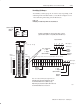
You select 1/2-slot addressing by setting switches 5 and 6 of the I/O
chassis backplane switch assembly:
• switch 5 to the OFF position
• switch 6 to the ON position
With 1/2-slot addressing, since 32 inputs bits AND 32 output bits are
available in the processor’s image table for each I/O group, you can
mix 8, 16 and 32-point I/O modules in any order in the I/O chassis.
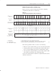
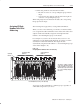
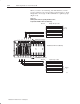
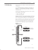
Figure 3.17 illustrates the 1/2-slot addressing concept with a 32-point
I/O module. A 32-point I/O module (with 1/2-slot I/O groups) uses
two words of the image table. When you use 8 and 16-point I/O
modules with 1/2-slot addressing, you get fewer total I/O points.
Figure 3.17
1/2Ćslot Addressing Concept
#%)( $&
)(%)( $&
" !
$&' !!$(
$& &$)%
#%)( $&
)(%)( $&
" !
$&' !!$(
$& &$)%
#)'
#)'
%$ #( #%)( $)!
'!$(
&$)%
'!$(
&$)%
'!$(
&$)%
'!$(
&$)%
#%)(
#%)(
1/2Ć Slot Addressing