
User Manual Owner's manual

3–14 Addressing Modes for Your Remote I/O
'&"! $'$(
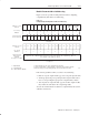
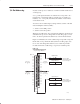
Thirty-two-point I/O modules need 32 input or 32 output bits in the
processor’s image table. Because only 16 input and 16 output bits
are available for each I/O group, to address a 32-point I/O module,
the remote I/O adapter module uses the unused input or output word
associated with the adjacent I/O slot.
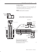
Refer to Figure 3.12. When the 1771-ASB remote adapter module
addresses a 1-slot I/O group containing a 32-point I/O module, the
adapter module uses the unused word assigned to the adjacent I/O
module slot. For example, the adapter module uses the unused input
word associated with I/O slot 1 (because that slot must hold an
output module and does not use its input word).
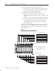
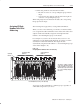
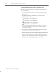
Figure 3.13 illustrates the concept of 1-slot addressing with two
32-point I/O modules.
Figure 3.12
1Ćslot I/O Group Concept With 32Ćpoint I/O Modules
#"!& "'%
!#'& "$
'&#'& "$
"$% "&
"$ $"'#
!#'& "$
'&#'& "$
"$% "&
"$ $"'#
"&
!#'& "'
$"'#
"&
'&#'& "'
$"'#